AD 2 AERODROMES
WSSS — SINGAPORE / SINGAPORE CHANGI INTL
WSSS AD 2.1 AERODROME LOCATION INDICATOR AND NAME
WSSS — SINGAPORE / SINGAPORE CHANGI INTL
WSSS AD 2.2 AERODROME GEOGRAPHICAL AND ADMINISTRATIVE DATA
| 1 | ARP coordinates and site at AD | 012133.16N 1035921.57E (Control Tower) |
| 2 | Direction and distance from (city) | 061°, 17.2km from City Centre (The Fullerton, Singapore) |
| 3 | Elevation/Reference temperature | 6.66 M (21.85ft) / 32.6 C |
| 4 | Geoid Undulation (AD elevation position) | 10.29 M |
| 5 | MAG VAR /Annual change | 0°26' E (2015) / negligible |
| 6 | AD Administration, address, telephone, telefax, AFS | |
RWY 02L/20R and RWY 02C/20C | ||
| 7 | Types of traffic permitted | IFR |
| 8 | Remarks | |
| ||
WSSS AD 2.3 OPERATIONAL HOURS
| Operational Hours | ||
|---|---|---|
| 1 | Aerodrome Administration: RWY 02L/20R and RWY 02C/20C | H24 |
| 2 | Customs and Immigration | H24 |
| 3 | Health and Sanitation | H24 |
| 4 | AIS Briefing Office | H24 |
| 5 | ATS Reporting Office | H24 |
| 6 | MET Briefing Office | H24 |
| 7 | Air Traffic Services | H24 |
WSSS AD 2.4 HANDLING SERVICES AND FACILITIES
| 1 | Cargo Handling Facilities | Cargo terminals equipped with advanced storage stacker, material and pallet container handling systems, computerised cargo information, data and documentation systems. Forklift (10 tonnes), Aircraft Main Deck Loaders (27 tonnes), trailers (e.g. 20-40 containers) on hire from hauliers. |
| 2 | Fuel / Oil Types | JET A1(for jet aircraft), Engine Oil - 2380, MJ02, 750, ET025. Lubricating Oil - Aeroshell 390, 750. Hydraulic Oil - Skydrol LD4, 500B4, 500B, Hyjet IV |
| 3 | Fuelling Facilities / Capacity | No limitation. H24 service. |
| 4 | Hangar space for visiting aircraft | By arrangement with SIA Engineering Company (SIAEC) or ST Aerospace Services Co. Maintenance hangars with multiple aircraft stands to accommodate up to A380 size aircraft. |
| 5 | Repair facilities for visiting aircraft | Major and minor maintenance and repairs for commercial aircraft up to and including A380, subject to availability of specialised equipment/ spares/toolings. |
| 6 | Remarks |
|
WSSS AD 2.5 PASSENGER FACILITIES
| 1 | Hotels | Rooms available inside transit area, adjacent to airport terminal and in the city but advisable advance booking. |
| 2 | Restaurants | Available in both transit and public areas. |
| 3 | Transportation | Buses, taxis and MRT train. Car rental service is available from 0700-2300 hrs daily |
| 4 | Medical Facilities | Avbl H24 at Airport Clinic. Ambulance. General Hospitals located at Simei (12km) and City (23km). |
| 5 | Bank and Post Office | Available at airport |
| 6 | Tourist Office | Available at airport |
| 7 | Remarks | Internet address : http://www.changiairport.com.sg for airport and flight information, shops and restaurants, facilities and services, flight connections and tourist information. |
WSSS AD 2.6 RESCUE AND FIRE FIGHTING SERVICES
| 1 | AD category for fire fighting | CAT10 (No facilities for foaming of runways) |
| 2 | Rescue equipment | Adequately provided as recommended by ICAO. |
| 3 | Capability for removal of disabled aircraft | Four 25-ton (Type G) and two 40-ton (Type F) pneumatic elevators, two 80-ton hydraulic recovery jacks, one set of tethering equipment and other accessory equipment. Capable of handling all wide-bodied aircraft. Provided by SIA at Tel:(65)65416329 or (65)65427116. |
| 4 | Remarks | All Airport Emergency Service personnel are trained in rescue and fire-fighting as well as medical first-aid. |
WSSS AD 2.7 SEASONAL AVAILABILITY - CLEARING
| There is no requirement for clearing. The aerodrome is available throughout the year. |
WSSS AD 2.8 APRONS, TAXIWAYS AND CHECK LOCATIONS/POSITIONS DATA
| 1 | Apron surface and strength | RWY 02L/20R RWY 02C/20C | Surface: Strength: | Concrete PCN 85/R/B/W/U |
| 2 | Taxiway width, surface and strength | RWY 02L/20R RWY 02C/20C | Width: | 45m (147ft) Taxiway V2; 35m (115ft) Taxiways NC3, EP and WP; 25m (82ft) Taxiway EP (from Taxilanes B1 and B3); 23m (75ft) Taxiway SA; 30m (100ft) All other Taxiways |
| Surface: | Cement Concrete - Taxiways W1, W9, E1, E3, E11 and EP (between E10 and E11); Bituminous Concrete - All other Taxiways | |||
| Strength: | PCN 85/R/B/W/U - Taxiways W1, W9, E1, E3, E11 and EP (between E10 and E11); PCN 72/F/B/W/U - All other Taxiways | |||
| 3 | ACL location and elevation | See AD-2.WSSS-ADC-2/Chart (flip side) for coordinates and elevations of aircraft stands. | ||
| 4 | INS checkpoints | |||
| 5 | Remarks | NIL | ||
WSSS AD 2.9 SURFACE MOVEMENT GUIDANCE AND CONTROL SYSTEM AND MARKINGS
| 1 | Use of aircraft stand ID signs, TWY guidelines and visual docking/parking guidance system of aircraft stands. |
Taxiing guidance signs at all intersections with TWY and RWY at all holding positions. Guidelines at apron. Nose-in guidance at aircraft stands. For information on Safegate Aircraft Docking Guidance System, Aircraft Parking Restrictions, Procedures for Start-up and Pushback of Aircraft, Pushback Procedures for Aircraft (Diagrams), Taxiing Guidance System at Singapore Changi Airport, refer to WSSS AD 2-9. Aircraft stand manoeuvring guidance lights are provided at aircraft stands 1 to 17, 101 to 104 and aircraft stands at Terminal 3. | |
| 2 | RWY and TWY markings and LGT |
RWY 02L/02C and RWY 20C RWY LGT: refer to WSSS AD 2-14 to WSSS AD 2-15. TWY LGT: Blue LGT on TWY curved edges, selected straight TWY edge sections and apron TWY edges only. Blue TWY edge markers along selected straight TWY edge sections. Red stop bar at TWY INT controllable on/off. Red stop bar LGT at TWY HLDG PSN entrances to RWY are controllable on/off and are supplemented with elevated RWY guard LGT at the sides. MARKING AIDS: THR, touchdown zone, centre line, side stripe, RWY designations, aiming point markings, TWY centre line, taxi holding positions - all taxiways, apron guide lines. | |
RWY 20R RWY LGT: refer to WSSS AD 2-14 to WSSS AD 2-15. TWY LGT: same as for RWY 02L/02C and RWY 20C. MARKING AIDS: Pre-threshold centre-line, transverse stripe for displaced THR, RWY designations, THR, touchdown zone, aiming point marking, RWY centre-line and stripe marking aids. | |
| 3 | Stop bars: Stop bars where appropriate. |
| 4 | Remarks: Nil |
1 SAFEGATE AIRCRAFT DOCKING GUIDANCE SYSTEM - SAFEDOCK
1.1 INTRODUCTION
1.2 DESCRIPTION OF SYSTEM
| LED DISPLAY AND LASER SCANNING UNIT | |
|---|---|
.jpg?s=CA47A16B72335A0DDB8841028A909427DA6E1F9B) | |
| Safedock Type 1 | Safedock Type 2 |
| Figure A | |
1.3 DOCKING PROCEDURES
| Safedock Type 1 | Safedock Type 2 | |||
|---|---|---|---|---|
| 1.3.1 | Check that the correct aircraft type is displayed. The scrolling arrows indicate that the system is activated (see figure 1). | .jpg?s=C2329B81741A613EE4251034BC5E9FA8ACF6B439) Figure 1: Figure 1:System tracking for aircraft. | ||
| 1.3.2 | Follow the lead-in line | |||
| 1.3.3 | When the aircraft has been caught by the scanning unit, the scanning unit checks that the aircraft is the correct type and the display provides azimuth guidance information. When the solid yellow closing rate bar appears, the aircraft is being tracked by the system. (see figure 2). | .jpg?s=81C0DA8B38C8700E67DC2A8523CCB7C72E4CFEAE) Figure 2: Figure 2:Aircraft tracked by the system. .jpg?s=2886D203EFCFEB57E354C61B6F3979C271E01772) | ||
| 1.3.4 | Look for the flashing red arrow and solid yellow arrow which provide azimuth guidance information. The flashing red arrow shows which direction to steer, while the solid yellow arrow gives an indication of how far the aircraft is off the centreline (see figures 2 and 3). | |||
| 1.3.5 | When the aircraft is 15m from the stop position, closing rate information is given. “Distance to go” is indicated by turning off one row of LEDs (Laser Electronic Displays) for every half metre that the aircraft advances towards the stop position. From 15m to the stop position, a digital display will indicate the distance from the stop position for every 1m. At 3m from the stop position, the display will indicate the distance from the stop position for every 0.2m (see figures 3 and 4). | .jpg?s=068171BBB45E18DE8440C788CEC0ECD536FFCE81) Figure 3 Figure 3LED closing rate bar starts diminishing when the aircraft is 15m from stopbar at one row for every 0.5m that the aircraft moves forward. | ||
| 1.3.6 | When the correct stop position is reached, all of the LEDs for the closing rate bar will be off, the word “STOP” will appear in the display. For Safedock Type 1 ADGS, the word “STOP” will be displayed in red with red border. For Safedock Type 2 ADGS, the word “STOP” will be displayed in yellow and two red, rectangular fields will light in the azimuth guidance area of the display (see figure 5). | .jpg?s=0F98162E42212232A9BC3FFAE07577A59321F4BF) Figure 4 Figure 4LED closing rate bar getting shorter as aircraft moves nearer to stopbar. | ||
| 1.3.7 | If the aircraft stops in the correct position, “OK” will be displayed after a few seconds (see figure 6). | .jpg?s=7FA162835DFDDDD82FEF4F4811BDC1FF884CA8E6) Figure 5 Figure 5Pilot to stop aircraft when “STOP” is displayed. | ||
.jpg?s=9264AE3587E72F71DBF21663267EA50C3B290885) Figure 6 Figure 6Informs the pilot that everything is in order and he can shutdown engine. | ||||
| 1.3.8 | If the aircraft has gone past the correct stop position, the display will show “TOO FAR” (see figure 7). | .jpg?s=4CE7746FB0065BBDF6B20AB7CAE1B0DAE6D0379E) Figure 7 Figure 7Indicates that the aircraft has gone beyond the stopbar. Pilot to check with ground engineer on the next move. | ||
| 1.3.9 | If some object is blocking the view towards the approaching aircraft or the detected aircraft is lost before 12m to the correct stop position, the system will show “WAIT” (see figure 8). | |||
| 1.3.10 | The aircraft must be identified at least 12m before the correct stop position. Otherwise, the display will show “WAIT”, “STOP” and “ID FAIL” (see figures 8, 9 and 10). | .jpg?s=345C914370EA1E4B0814784B4F91F4A92B47CB1E) Figure 8 Figure 8Pilot to hold aircraft and wait for other instructions from the display. | ||
1.4 SAFETY MEASURES
| Safedock Type 1 | Safedock Tye 2 | |||
|---|---|---|---|---|
| 1.4.1 | Pilot should not turn an aircraft into the parking stand if the docking system is not activated or on seeing a wrong aircraft type displayed on the system. | .jpg?s=AF1881B4B9F611F68DCA050761066B92592B50B8) Figure 9 Figure 9“STOP" may appear suddenly in the process of docking. Pilot to stop immediately and wait for further instructions. | ||
| 1.4.2 | Pilot should not proceed beyond the passenger loading bridges unless the scrolling arrows (see figure 1) have been superseded by the solid yellow closing rate bar (see figure 2). | |||
| 1.4.3 | When using the docking system, pilots are to taxi into the aircraft stand at minimum speed. The system will display “SLOW” to inform the pilot if the aircraft' | .jpg?s=A9948A2A039E8C04F8E9925D772AF8173CE29F3F) Figure 10 Figure 10Indicates the system fails to identify the aircraft. | ||
| 1.4.4 | In bad weather conditions, the docking system may go into downgrade mode. The display will show the aircraft type and “SLOW” and the scrolling arrows are disabled (see figure 12). When the system has detected the aircraft, the solid yellow closing rate bar appears. Docking process is allowed to continue but pilots should exercise caution. | .jpg?s=295CA45CEAD7516C4ABF8350B7BD034DE748A3A6) Figure 11 Figure 11Informs the pilot that the aircraft travelling speed is too fast. Pilot to slow down the speed. Similar for both Safedock Type 1 and Type 2 | ||
| 1.4.5 | To avoid overshooting, pilots are advised to approach the stop position slowly and observe the closing rate information displayed. Pilots should stop the aircraft immediately when seeing the “STOP” or “WAIT” display, when given the stop sign by the aircraft marshaller or is unsure of the information displayed during the docking process. |  Figure 12 Figure 12The system goes into ‘downgrade’ mode due to bad weather conditions, pilot will be prompted to slow down. Docking process will continue when the aircraft is detected but pilot should exercise caution. | ||
| 1.4.6 | Pilot should stop the aircraft immediately if the display goes black during the docking process. The aircraft is to be marshalled into the stand manually. | |||
2 AIRCRAFT PARKING RESTRICTIONS
2.1 TERMINAL 1 AIRCRAFT STANDS
| Stands | C1 | C11 | C13 | C15 | C16 | C17 | C18 | C19 | C20 | C22 | C23 | C24 | C25 | C26 |
|---|---|---|---|---|---|---|---|---|---|---|---|---|---|---|
| A300 | ✈ | ✈ | ✈ | ✈ | ✈ | ✈ | ✈ | ✈ | ✈ | |||||
| A310 | ✈ | ✈ | ✈ | ✈ | ✈ | ✈ | ✈ | ✈ | ✈ | ✈ | ✈ | |||
| A319 | ✈ | ✈ | ✈ | ✈ | ✈ | ✈ | ✈ | ✈ | ✈ | ✈ | ✈ | ✈ | ✈ | ✈ |
| A320 | ✈ | ✈ | ✈ | ✈ | ✈ | ✈ | ✈ | ✈ | ✈ | ✈ | ✈ | ✈ | ✈ | ✈ |
| A321 | ✈ | ✈ | ✈ | ✈ | ✈ | ✈ | ✈ | ✈ | ✈ | ✈ | ✈ | ✈ | ✈ | ✈ |
| A332 | ✈ | ✈ | ✈ | ✈ | ✈ | ✈ | ✈ | ✈ | ✈ | ✈ | ✈ | |||
| A333 | ✈ | ✈ | ✈ | ✈ | ✈ | ✈ | ✈ | ✈ | ✈ | ✈ | ✈ | |||
| A342 | ✈ | ✈ | ✈ | ✈ | ✈ | ✈ | ✈ | ✈ | ✈ | ✈ | ✈ | |||
| A343 | ✈ | ✈ | ✈ | ✈ | ✈ | ✈ | ✈ | ✈ | ✈ | ✈ | ✈ | |||
| A345 | ✈ | ✈ | ✈ | ✈ | ✈ | ✈ | ✈ | ✈ | ✈ | |||||
| A346 | ✈ | ✈ | ✈ | |||||||||||
| A359 | ✈ | ✈ | ✈ | ✈ | ✈ | ✈ | ✈ | ✈ | ✈ | |||||
| A380 | ✈ | ✈ | ✈ | |||||||||||
| B707 | ✈ | ✈ | ✈ | |||||||||||
| B717 | ✈ | ✈ | ✈ | ✈ | ✈ | ✈ | ✈ | |||||||
| B727 | ✈ | ✈ | ✈ | |||||||||||
| B737 | ✈ | ✈ | ✈ | ✈ | ✈ | ✈ | ✈ | ✈ | ✈ | ✈ | ✈ | ✈ | ✈ | ✈ |
| B747 | ✈ | ✈ | ✈ | ✈ | ✈ | ✈ | ✈ | ✈ | ✈ | |||||
| B74S | ✈ | ✈ | ✈ | ✈ | ✈ | |||||||||
| B757 | ✈ | ✈ | ✈ | ✈ | ✈ | ✈ | ✈ | ✈ | ✈ | ✈ | ✈ | |||
| B762 | ✈ | ✈ | ✈ | ✈ | ✈ | ✈ | ✈ | ✈ | ✈ | ✈ | ✈ | ✈ | ||
| B763 | ✈ | ✈ | ✈ | ✈ | ✈ | ✈ | ✈ | ✈ | ✈ | ✈ | ✈ | ✈ | ||
| B772 | ✈ | ✈ | ✈ | ✈ | ✈ | ✈ | ✈ | ✈ | ✈ | ✈ | ✈ | |||
| B773 | ✈ | ✈ | ✈ | ✈ | ✈ | ✈ | ✈ | ✈ | ✈ | |||||
| B773ER | ✈ | ✈ | ✈ | ✈ | ✈ | ✈ | ✈ | ✈ | ✈ | |||||
| B788 | ✈ | ✈ | ✈ | ✈ | ✈ | ✈ | ✈ | ✈ | ✈ | |||||
| B789 | ✈ | ✈ | ✈ | ✈ | ✈ | ✈ | ✈ | ✈ | ✈ | ✈ | ||||
| BA146 | ✈ | |||||||||||||
| DC10 | ✈ | ✈ | ✈ | ✈ | ✈ | ✈ | ||||||||
| DC9 | ✈ | ✈ | ||||||||||||
| F100 | ✈ | ✈ | ✈ | ✈ | ✈ | ✈ | ✈ | |||||||
| IL62 | ✈ | ✈ | ✈ | ✈ | ✈ | ✈ | ✈ | ✈ | ||||||
| IL86 | ✈ | ✈ | ✈ | ✈ | ✈ | ✈ | ✈ | ✈ | ||||||
| IL96 | ✈ | ✈ | ✈ | ✈ | ✈ | ✈ | ✈ | ✈ | ||||||
| L101 | ✈ | ✈ | ✈ | ✈ | ✈ | ✈ | ||||||||
| MD11 | ✈ | ✈ | ✈ | ✈ | ✈ | ✈ | ✈ | ✈ | ✈ | |||||
| MD80/82 | ✈ | ✈ | ✈ | ✈ | ✈ | ✈ | ✈ | ✈ | ✈ | |||||
| MD83 | ✈ | ✈ | ✈ | ✈ | ✈ | ✈ | ||||||||
| MD88 | ✈ | ✈ | ✈ | ✈ | ✈ | ✈ | ✈ | ✈ | ✈ |
2.2 TERMINAL 1 AIRCRAFT STANDS
| Stands | D30 | D32 | D34 | D35 | D36 | D37 | D38 | D40 | D41 | D42 | D42L & D42R | D44 | D46 | D47 | D48 | D49 |
|---|---|---|---|---|---|---|---|---|---|---|---|---|---|---|---|---|
| A300 | ✈ | ✈ | ✈ | ✈ | ✈ | ✈ | ✈ | ✈ | ✈ | ✈ | ✈ | |||||
| A310 | ✈ | ✈ | ✈ | ✈ | ✈ | ✈ | ✈ | ✈ | ✈ | ✈ | ✈ | |||||
| A319 | ✈ | ✈ | ✈ | ✈ | ✈ | ✈ | ✈ | ✈ | ✈ | ✈ | ✈ | ✈ | ✈ | ✈ | ✈ | |
| A320 | ✈ | ✈ | ✈ | ✈ | ✈ | ✈ | ✈ | ✈ | ✈ | ✈ | ✈ | ✈ | ✈ | ✈ | ✈ | |
| A321 | ✈ | ✈ | ✈ | ✈ | ✈ | ✈ | ✈ | ✈ | ✈ | ✈ | ✈ | ✈ | ✈ | ✈ | ✈ | |
| A332 | ✈ | ✈ | ✈ | ✈ | ✈ | ✈ | ✈ | ✈ | ✈ | ✈ | ✈ | ✈ | ||||
| A333 | ✈ | ✈ | ✈ | ✈ | ✈ | ✈ | ✈ | ✈ | ✈ | ✈ | ✈ | ✈ | ||||
| A342 | ✈ | ✈ | ✈ | ✈ | ✈ | ✈ | ✈ | ✈ | ✈ | ✈ | ✈ | |||||
| A343 | ✈ | ✈ | ✈ | ✈ | ✈ | ✈ | ✈ | ✈ | ✈ | ✈ | ✈ | ✈ | ||||
| A345 | ✈ | ✈ | ✈ | ✈ | ✈ | ✈ | ✈ | ✈ | ✈ | |||||||
| A346 | ✈ | ✈ | ✈ | ✈ | ||||||||||||
| A359 | ✈ | ✈ | ✈ | ✈ | ✈ | ✈ | ✈ | ✈ | ✈ | ✈ | ||||||
| A380 | ✈ | ✈ | ||||||||||||||
| B707 | ✈ | ✈ | ✈ | |||||||||||||
| B717 | ✈ | ✈ | ✈ | ✈ | ✈ | ✈ | ✈ | ✈ | ✈ | ✈ | ||||||
| B727 | ✈ | ✈ | ✈ | |||||||||||||
| B737 | ✈ | ✈ | ✈ | ✈ | ✈ | ✈ | ✈ | ✈ | ✈ | ✈ | ✈ | ✈ | ✈ | ✈ | ✈ | |
| B747 | ✈ | ✈ | ✈ | ✈ | ✈ | ✈ | ✈ | ✈ | ✈ | |||||||
| B74S | ✈ | ✈ | ✈ | ✈ | ✈ | ✈ | ✈ | |||||||||
| B757 | ✈ | ✈ | ✈ | ✈ | ✈ | ✈ | ✈ | ✈ | ✈ | ✈ | ✈ | |||||
| B762 | ✈ | ✈ | ✈ | ✈ | ✈ | ✈ | ✈ | ✈ | ✈ | ✈ | ✈ | ✈ | ✈ | |||
| B763 | ✈ | ✈ | ✈ | ✈ | ✈ | ✈ | ✈ | ✈ | ✈ | ✈ | ✈ | ✈ | ✈ | |||
| B772 | ✈ | ✈ | ✈ | ✈ | ✈ | ✈ | ✈ | ✈ | ✈ | ✈ | ✈ | ✈ | ||||
| B773 | ✈ | ✈ | ✈ | ✈ | ✈ | ✈ | ||||||||||
| B773ER | ✈ | ✈ | ✈ | ✈ | ✈ | ✈ | ||||||||||
| B788 | ✈ | ✈ | ✈ | ✈ | ✈ | ✈ | ✈ | ✈ | ||||||||
| B789 | ✈ | ✈ | ✈ | ✈ | ✈ | ✈ | ✈ | ✈ | ✈ | ✈ | ||||||
| BA146 | ✈ | |||||||||||||||
| DC10 | ✈ | ✈ | ✈ | ✈ | ✈ | ✈ | ✈ | ✈ | ||||||||
| DC9 | ✈ | |||||||||||||||
| F100 | ✈ | ✈ | ✈ | ✈ | ✈ | ✈ | ✈ | ✈ | ✈ | |||||||
| IL62 | ✈ | ✈ | ✈ | ✈ | ✈ | ✈ | ✈ | ✈ | ✈ | ✈ | ||||||
| IL86 | ✈ | ✈ | ✈ | ✈ | ✈ | ✈ | ✈ | ✈ | ✈ | ✈ | ||||||
| IL96 | ✈ | ✈ | ✈ | ✈ | ✈ | ✈ | ✈ | ✈ | ✈ | ✈ | ||||||
| L101 | ✈ | ✈ | ✈ | ✈ | ✈ | ✈ | ✈ | ✈ | ||||||||
| MD11 | ✈ | ✈ | ✈ | ✈ | ✈ | ✈ | ✈ | ✈ | ||||||||
| MD80 | ✈ | ✈ | ✈ | ✈ | ✈ | ✈ | ✈ | ✈ | ✈ | ✈ | ✈ | |||||
| MD82 | ✈ | ✈ | ✈ | ✈ | ✈ | ✈ | ✈ | ✈ | ✈ | ✈ | ✈ | |||||
| MD83 | ✈ | ✈ | ✈ | ✈ | ✈ | ✈ | ✈ | ✈ | ✈ | ✈ | ✈ | ✈ | ✈ | ✈ | ||
| MD88 | ✈ | ✈ | ✈ | ✈ | ✈ | ✈ | ✈ | ✈ | ✈ | ✈ | ✈ | |||||
| YK42 | ✈ |
2.3 TERMINAL 2 AIRCRAFT STANDS
| Stands | E1 | E2 | E3 | E4 | E5 | E6 | E7 | E8 | E10 | E11 | E12 | E20 | E22 | E24 | E24L | E24R | E26 | E27 | E28 |
|---|---|---|---|---|---|---|---|---|---|---|---|---|---|---|---|---|---|---|---|
| A300 | ✈ | ✈ | ✈ | ✈ | ✈ | ✈ | ✈ | ✈ | ✈ | ✈ | ✈ | ✈ | ✈ | ||||||
| A310 | ✈ | ✈ | ✈ | ✈ | ✈ | ✈ | ✈ | ✈ | ✈ | ✈ | ✈ | ✈ | ✈ | ✈ | ✈ | ||||
| A319 | ✈ | ✈ | ✈ | ✈ | ✈ | ✈ | ✈ | ✈ | ✈ | ✈ | ✈ | ✈ | ✈ | ✈ | ✈ | ✈ | ✈ | ✈ | |
| A320 | ✈ | ✈ | ✈ | ✈ | ✈ | ✈ | ✈ | ✈ | ✈ | ✈ | ✈ | ✈ | ✈ | ✈ | ✈ | ✈ | ✈ | ||
| A321 | ✈ | ✈ | ✈ | ✈ | ✈ | ✈ | ✈ | ✈ | |||||||||||
| A332 | ✈ | ✈ | ✈ | ✈ | ✈ | ✈ | ✈ | ✈ | ✈ | ✈ | ✈ | ✈ | |||||||
| A333 | ✈ | ✈ | ✈ | ✈ | ✈ | ✈ | ✈ | ✈ | ✈ | ✈ | ✈ | ✈ | |||||||
| A342 | ✈ | ✈ | ✈ | ✈ | ✈ | ✈ | ✈ | ✈ | ✈ | ✈ | ✈ | ||||||||
| A343 | ✈ | ✈ | ✈ | ✈ | ✈ | ✈ | ✈ | ✈ | ✈ | ✈ | ✈ | ||||||||
| A345 | ✈ | ✈ | ✈ | ✈ | ✈ | ✈ | ✈ | ✈ | ✈ | ✈ | ✈ | ||||||||
| A346 | ✈ | ✈ | ✈ | ||||||||||||||||
| A359 | ✈ | ✈ | ✈ | ✈ | ✈ | ✈ | ✈ | ✈ | ✈ | ✈ | ✈ | ✈ | |||||||
| A380 | ✈ | ✈ | ✈ | ||||||||||||||||
| B707 | ✈ | ✈ | ✈ | ||||||||||||||||
| B727 | ✈ | ✈ | ✈ | ✈ | ✈ | ✈ | ✈ | ✈ | ✈ | ✈ | ✈ | ✈ | ✈ | ✈ | |||||
| B737 | ✈ | ✈ | ✈ | ✈ | ✈ | ✈ | ✈ | ✈ | ✈ | ✈ | ✈ | ✈ | ✈ | ✈ | ✈ | ✈ | ✈ | ||
| B747 | ✈ | ✈ | ✈ | ✈ | ✈ | ✈ | ✈ | ✈ | ✈ | ✈ | ✈ | ✈ | |||||||
| B748 | ✈ | ✈ | ✈ | ||||||||||||||||
| B74S | ✈ | ✈ | ✈ | ✈ | ✈ | ✈ | ✈ | ✈ | ✈ | ✈ | |||||||||
| B757 | ✈ | ✈ | ✈ | ✈ | ✈ | ✈ | ✈ | ✈ | ✈ | ✈ | ✈ | ✈ | ✈ | ✈ | |||||
| B762 | ✈ | ✈ | ✈ | ✈ | ✈ | ✈ | ✈ | ✈ | ✈ | ✈ | ✈ | ✈ | ✈ | ✈ | ✈ | ||||
| B763 | ✈ | ✈ | ✈ | ✈ | ✈ | ✈ | ✈ | ✈ | ✈ | ✈ | ✈ | ✈ | ✈ | ✈ | ✈ | ||||
| B772 | ✈ | ✈ | ✈ | ✈ | ✈ | ✈ | ✈ | ✈ | ✈ | ✈ | ✈ | ✈ | |||||||
| B772LR | ✈ | ✈ | |||||||||||||||||
| B773 | ✈ | ✈ | ✈ | ✈ | ✈ | ✈ | ✈ | ✈ | ✈ | ✈ | |||||||||
| B773ER | ✈ | ✈ | ✈ | ✈ | ✈ | ✈ | ✈ | ✈ | ✈ | ||||||||||
| B788 | ✈ | ✈ | ✈ | ✈ | ✈ | ✈ | ✈ | ✈ | ✈ | ✈ | ✈ | ✈ | |||||||
| B789 | ✈ | ✈ | ✈ | ✈ | ✈ | ✈ | ✈ | ✈ | ✈ | ✈ | ✈ | ✈ | |||||||
| DC10 | ✈ | ✈ | ✈ | ✈ | ✈ | ✈ | ✈ | ✈ | ✈ | ||||||||||
| DC9 | ✈ | ||||||||||||||||||
| F70 | ✈ | ✈ | ✈ | ✈ | ✈ | ✈ | ✈ | ✈ | ✈ | ✈ | ✈ | ✈ | ✈ | ||||||
| F100 | ✈ | ✈ | ✈ | ||||||||||||||||
| IL62 | ✈ | ✈ | ✈ | ||||||||||||||||
| IL86 | ✈ | ✈ | ✈ | ||||||||||||||||
| IL96 | ✈ | ✈ | ✈ | ||||||||||||||||
| L101 | ✈ | ✈ | ✈ | ✈ | ✈ | ✈ | ✈ | ✈ | ✈ | ||||||||||
| MD11 | ✈ | ✈ | ✈ | ✈ | ✈ | ✈ | ✈ | ✈ | ✈ | ||||||||||
| MD80 | ✈ | ✈ | ✈ | ||||||||||||||||
| MD82 | ✈ | ✈ | ✈ | ||||||||||||||||
| MD83 | ✈ | ✈ | ✈ | ||||||||||||||||
| MD87 | ✈ | ||||||||||||||||||
| MD88 | ✈ | ✈ | ✈ |
2.4 TERMINAL 2 AIRCRAFT STANDS
| Stands | F30 | F31 | F32 | F33 | F34 | F35 | F36 | F37 | F40 | F41 | F42 | F50 | F52 | F54 | F56 | F58 | F59 | F60 |
|---|---|---|---|---|---|---|---|---|---|---|---|---|---|---|---|---|---|---|
| A300 | ✈ | ✈ | ✈ | ✈ | ✈ | ✈ | ✈ | ✈ | ✈ | ✈ | ✈ | ✈ | ✈ | |||||
| A310 | ✈ | ✈ | ✈ | ✈ | ✈ | ✈ | ✈ | ✈ | ✈ | ✈ | ✈ | ✈ | ✈ | ✈ | ||||
| A319 | ✈ | ✈ | ✈ | ✈ | ✈ | ✈ | ✈ | ✈ | ✈ | ✈ | ✈ | ✈ | ✈ | ✈ | ||||
| A320 | ✈ | ✈ | ✈ | ✈ | ✈ | ✈ | ✈ | ✈ | ✈ | ✈ | ✈ | ✈ | ✈ | ✈ | ||||
| A332 | ✈ | ✈ | ✈ | ✈ | ✈ | ✈ | ✈ | ✈ | ✈ | ✈ | ✈ | ✈ | ||||||
| A333 | ✈ | ✈ | ✈ | ✈ | ✈ | ✈ | ✈ | ✈ | ✈ | ✈ | ✈ | ✈ | ||||||
| A342 | ✈ | ✈ | ✈ | ✈ | ✈ | ✈ | ✈ | ✈ | ✈ | ✈ | ✈ | |||||||
| A343 | ✈ | ✈ | ✈ | ✈ | ✈ | ✈ | ✈ | ✈ | ✈ | ✈ | ✈ | |||||||
| A345 | ✈ | ✈ | ✈ | ✈ | ✈ | ✈ | ✈ | ✈ | ✈ | ✈ | ✈ | |||||||
| A346 | ✈ | ✈ | ||||||||||||||||
| A359 | ✈ | ✈ | ✈ | ✈ | ✈ | ✈ | ✈ | ✈ | ✈ | |||||||||
| A380 | ✈ | ✈ | ✈ | |||||||||||||||
| B707 | ✈ | ✈ | ✈ | ✈ | ||||||||||||||
| B727 | ✈ | ✈ | ✈ | ✈ | ✈ | ✈ | ✈ | ✈ | ✈ | ✈ | ✈ | ✈ | ✈ | ✈ | ✈ | |||
| B737 | ✈ | ✈ | ✈ | ✈ | ✈ | ✈ | ✈ | ✈ | ✈ | ✈ | ✈ | ✈ | ✈ | ✈ | ||||
| B747 | ✈ | ✈ | ✈ | ✈ | ✈ | ✈ | ✈ | ✈ | ✈ | ✈ | ✈ | ✈ | ||||||
| B748 | ✈ | ✈ | ✈ | |||||||||||||||
| B74S | ✈ | ✈ | ✈ | ✈ | ✈ | ✈ | ✈ | ✈ | ✈ | ✈ | ||||||||
| B757 | ✈ | ✈ | ✈ | ✈ | ✈ | ✈ | ✈ | ✈ | ✈ | ✈ | ✈ | ✈ | ✈ | ✈ | ||||
| B762 | ✈ | ✈ | ✈ | ✈ | ✈ | ✈ | ✈ | ✈ | ✈ | ✈ | ✈ | ✈ | ✈ | ✈ | ||||
| B763 | ✈ | ✈ | ✈ | ✈ | ✈ | ✈ | ✈ | ✈ | ✈ | ✈ | ✈ | ✈ | ✈ | ✈ | ||||
| B772 | ✈ | ✈ | ✈ | ✈ | ✈ | ✈ | ✈ | ✈ | ✈ | ✈ | ✈ | ✈ | ✈ | |||||
| B772LR | ✈ | ✈ | ✈ | |||||||||||||||
| B773 | ✈ | ✈ | ✈ | ✈ | ✈ | ✈ | ✈ | |||||||||||
| B773ER | ✈ | ✈ | ✈ | ✈ | ✈ | ✈ | ✈ | |||||||||||
| B788 | ✈ | ✈ | ✈ | ✈ | ✈ | ✈ | ✈ | ✈ | ✈ | ✈ | ✈ | ✈ | ||||||
| B789 | ✈ | ✈ | ✈ | ✈ | ✈ | ✈ | ✈ | ✈ | ✈ | ✈ | ✈ | ✈ | ||||||
| DC10 | ✈ | ✈ | ✈ | ✈ | ✈ | ✈ | ✈ | ✈ | ||||||||||
| DC9 | ✈ | ✈ | ✈ | ✈ | ||||||||||||||
| F70 | ✈ | ✈ | ✈ | ✈ | ✈ | ✈ | ✈ | ✈ | ✈ | ✈ | ✈ | ✈ | ✈ | ✈ | ✈ | |||
| L101 | ✈ | ✈ | ✈ | ✈ | ✈ | ✈ | ✈ | ✈ | ||||||||||
| MD11 | ✈ | ✈ | ✈ | ✈ | ✈ | ✈ | ✈ | ✈ | ||||||||||
| MD87 | ✈ | ✈ |
| Stands | F35L | F35R | F52L | F52R | F56L | F56R | F59L | F59R |
|---|---|---|---|---|---|---|---|---|
| A319 | ✈ | ✈ | ✈ | ✈ | ✈ | ✈ | ✈ | ✈ |
| A320 | ✈ | ✈ | ✈ | ✈ | ✈ | ✈ | ✈ | ✈ |
| A321 | ✈ | ✈ | ✈ | ✈ | ✈ | ✈ | ✈ | ✈ |
| B737 | ✈ | ✈ | ||||||
| B737(100-500) | ✈ | ✈ | ✈ | ✈ | ✈ | ✈ | ||
| B737(600-900) | ✈ | ✈ | ✈ | ✈ | ✈ | |||
| MD83 | ✈ | ✈ | ✈ | ✈ | ✈ | ✈ |
2.5 TERMINAL 3 AIRCRAFT STANDS
| Stands | A1 | A2 | A3 | A4 | A5 | A9 | A10 | A11 | A12 | A13 | A14 | A15 | A16 | A17 | A18 | A19 | A20 | A21 |
|---|---|---|---|---|---|---|---|---|---|---|---|---|---|---|---|---|---|---|
| A300 | ✈ | ✈ | ✈ | ✈ | ✈ | ✈ | ✈ | ✈ | ✈ | ✈ | ✈ | ✈ | ✈ | ✈ | ✈ | |||
| A310 | ✈ | ✈ | ✈ | ✈ | ✈ | ✈ | ✈ | ✈ | ✈ | ✈ | ✈ | ✈ | ✈ | ✈ | ✈ | |||
| A319 | ✈ | ✈ | ✈ | ✈ | ✈ | ✈ | ✈ | ✈ | ✈ | ✈ | ✈ | ✈ | ✈ | ✈ | ✈ | |||
| A320 | ✈ | ✈ | ✈ | ✈ | ✈ | ✈ | ✈ | ✈ | ✈ | ✈ | ✈ | ✈ | ✈ | ✈ | ✈ | |||
| A321 | ✈ | ✈ | ✈ | ✈ | ✈ | ✈ | ✈ | ✈ | ✈ | ✈ | ✈ | ✈ | ✈ | ✈ | ✈ | |||
| A332 | ✈ | ✈ | ✈ | ✈ | ✈ | ✈ | ✈ | ✈ | ✈ | ✈ | ✈ | ✈ | ✈ | ✈ | ✈ | ✈ | ✈ | |
| A333 | ✈ | ✈ | ✈ | ✈ | ✈ | ✈ | ✈ | ✈ | ✈ | ✈ | ✈ | ✈ | ✈ | ✈ | ✈ | ✈ | ✈ | ✈ |
| A343 | ✈ | ✈ | ✈ | ✈ | ✈ | ✈ | ✈ | ✈ | ✈ | ✈ | ✈ | ✈ | ✈ | ✈ | ✈ | ✈ | ✈ | |
| A345 | ✈ | ✈ | ✈ | ✈ | ✈ | ✈ | ✈ | ✈ | ✈ | ✈ | ✈ | ✈ | ||||||
| A346 | ✈ | ✈ | ✈ | ✈ | ✈ | ✈ | ✈ | ✈ | ||||||||||
| A359 | ✈ | ✈ | ✈ | ✈ | ✈ | ✈ | ✈ | ✈ | ✈ | ✈ | ✈ | ✈ | ||||||
| A380 | ✈ | ✈ | ✈ | ✈ | ||||||||||||||
| B737 | ✈ | ✈ | ✈ | ✈ | ✈ | ✈ | ✈ | ✈ | ✈ | ✈ | ||||||||
| B744 | ✈ | ✈ | ✈ | ✈ | ✈ | ✈ | ✈ | ✈ | ✈ | ✈ | ✈ | ✈ | ||||||
| B788 | ✈ | ✈ | ✈ | ✈ | ✈ | ✈ | ✈ | ✈ | ✈ | ✈ | ✈ | ✈ | ✈ | ✈ | ||||
| B789 | ✈ | ✈ | ✈ | ✈ | ✈ | ✈ | ✈ | ✈ | ✈ | ✈ | ✈ | ✈ | ✈ | ✈ | ✈ | ✈ | ||
| B757 | ✈ | ✈ | ✈ | ✈ | ✈ | ✈ | ✈ | ✈ | ✈ | ✈ | ✈ | ✈ | ✈ | ✈ | ✈ | |||
| B767 | ✈ | ✈ | ✈ | ✈ | ✈ | ✈ | ✈ | ✈ | ✈ | ✈ | ✈ | ✈ | ✈ | ✈ | ✈ | |||
| B772 | ✈ | ✈ | ✈ | ✈ | ✈ | ✈ | ✈ | ✈ | ✈ | ✈ | ✈ | ✈ | ✈ | ✈ | ✈ | ✈ | ✈ | ✈ |
| B772LR | ✈ | ✈ | ||||||||||||||||
| B773 | ✈ | ✈ | ✈ | ✈ | ✈ | ✈ | ✈ | ✈ | ||||||||||
| B773ER | ✈ | ✈ | ✈ | ✈ | ✈ | ✈ | ✈ | ✈ |
| Stands | B1 | B2 | B3 | B4 | B5 | B6 | B7 | B8 | B9 | B10 |
|---|---|---|---|---|---|---|---|---|---|---|
| A300 | ✈ | ✈ | ✈ | ✈ | ✈ | ✈ | ✈ | ✈ | ✈ | |
| A310 | ✈ | ✈ | ✈ | ✈ | ✈ | ✈ | ✈ | ✈ | ✈ | |
| A319 | ✈ | ✈ | ✈ | ✈ | ✈ | ✈ | ✈ | ✈ | ✈ | |
| A320 | ✈ | ✈ | ✈ | ✈ | ✈ | ✈ | ✈ | ✈ | ✈ | |
| A321 | ✈ | ✈ | ✈ | ✈ | ✈ | ✈ | ✈ | ✈ | ✈ | |
| A332 | ✈ | ✈ | ✈ | ✈ | ✈ | ✈ | ✈ | ✈ | ✈ | ✈ |
| A333 | ✈ | ✈ | ✈ | ✈ | ✈ | ✈ | ✈ | ✈ | ✈ | ✈ |
| A343 | ✈ | ✈ | ✈ | ✈ | ✈ | ✈ | ✈ | ✈ | ✈ | ✈ |
| A345 | ✈ | ✈ | ✈ | ✈ | ✈ | ✈ | ✈ | ✈ | ✈ | ✈ |
| A359 | ✈ | ✈ | ✈ | ✈ | ✈ | ✈ | ✈ | ✈ | ✈ | ✈ |
| A346 | ✈ | ✈ | ✈ | ✈ | ||||||
| A380 | ✈ | ✈ | ✈ | ✈ | ||||||
| B707 | ✈ | ✈ | ||||||||
| B737 | ✈ | ✈ | ||||||||
| B744 | ✈ | ✈ | ✈ | ✈ | ✈ | ✈ | ✈ | ✈ | ✈ | ✈ |
| B788 | ✈ | ✈ | ✈ | ✈ | ✈ | ✈ | ✈ | ✈ | ✈ | |
| B789 | ✈ | ✈ | ✈ | ✈ | ✈ | ✈ | ✈ | ✈ | ✈ | ✈ |
| B757 | ✈ | ✈ | ✈ | ✈ | ✈ | ✈ | ✈ | ✈ | ✈ | |
| B767 | ✈ | ✈ | ✈ | ✈ | ✈ | ✈ | ✈ | ✈ | ✈ | |
| B772 | ✈ | ✈ | ✈ | ✈ | ✈ | ✈ | ✈ | ✈ | ✈ | ✈ |
| B773 | ✈ | ✈ | ✈ | ✈ | ✈ | ✈ | ✈ | ✈ | ||
| B773ER | ✈ | ✈ | ✈ | ✈ | ✈ | ✈ | ✈ | ✈ |
2.6 REMOTE STANDS
| Stands | 103 | 104 | 200 | 200L | 200R | 201 | 202 | 202L | 202R | 203 | 205 | 206 | 207 | 208 | 209 |
|---|---|---|---|---|---|---|---|---|---|---|---|---|---|---|---|
| A300, A310 | ✈ | ✈ | ✈ | ✈ | ✈ | ✈ | ✈ | ✈ | ✈ | ✈ | ✈ | ||||
| A319, A320 | ✈ | ✈ | ✈ | ✈ | ✈ | ✈ | ✈ | ✈ | ✈ | ✈ | ✈ | ✈ | ✈ | ||
| A321 | ✈ | ✈ | ✈ | ✈ | |||||||||||
| A330, A342 | ✈ | ✈ | ✈ | ✈ | ✈ | ✈ | ✈ | ✈ | |||||||
| A343, A345 | ✈ | ✈ | ✈ | ✈ | ✈ | ✈ | ✈ | ✈ | |||||||
| A359 | ✈ | ✈ | ✈ | ✈ | ✈ | ✈ | ✈ | ✈ | |||||||
| A380 | ✈ | ✈ | |||||||||||||
| AT72 | ✈ | ✈ | ✈ | ✈ | ✈ | ✈ | ✈ | ✈ | ✈ | ||||||
| B707, B727 | ✈ | ✈ | ✈ | ✈ | ✈ | ✈ | ✈ | ✈ | ✈ | ✈ | ✈ | ||||
| B737 | ✈ | ✈ | ✈ | ✈ | ✈ | ✈ | ✈ | ✈ | ✈ | ✈ | ✈ | ✈ | ✈ | ||
| B747, B74S, B788 | ✈ | ✈ | ✈ | ✈ | ✈ | ✈ | ✈ | ✈ | |||||||
| B748 | ✈ | ✈ | |||||||||||||
| B757 | ✈ | ✈ | ✈ | ✈ | ✈ | ✈ | ✈ | ✈ | ✈ | ✈ | ✈ | ||||
| B767, B772, B773 | ✈ | ✈ | ✈ | ✈ | ✈ | ✈ | ✈ | ✈ | |||||||
| B773ER | ✈ | ✈ | ✈ | ✈ | ✈ | ✈ | ✈ | ✈ | |||||||
| B789 | ✈ | ✈ | ✈ | ✈ | ✈ | ✈ | ✈ | ✈ | |||||||
| DC8 | ✈ | ✈ | |||||||||||||
| DC10 | ✈ | ✈ | ✈ | ✈ | ✈ | ✈ | ✈ | ✈ | |||||||
| DHC7 | ✈ | ✈ | ✈ | ||||||||||||
| F70 | ✈ | ✈ | ✈ | ✈ | ✈ | ✈ | ✈ | ✈ | ✈ | ✈ | ✈ | ||||
| IL62 | ✈ | ✈ | ✈ | ✈ | ✈ | ✈ | |||||||||
| L101 | ✈ | ✈ | ✈ | ✈ | ✈ | ✈ | ✈ | ✈ | |||||||
| MD11 | ✈ | ✈ | ✈ | ✈ | ✈ | ✈ | ✈ | ✈ | |||||||
| MD83 | ✈ | ✈ | ✈ | ✈ | ✈ | ✈ | ✈ |
| Stands | 300 | 301 | 302 | 303 | 304 | 305 | 306 | 307 | 308 | 309 | 310 | 400 | 401 | 402 | 403 | 404 |
|---|---|---|---|---|---|---|---|---|---|---|---|---|---|---|---|---|
| A300, A310 | ✈ | ✈ | ✈ | ✈ | ✈ | ✈ | ✈ | ✈ | ✈ | ✈ | ✈ | ✈ | ||||
| A319, A320 | ✈ | ✈ | ✈ | ✈ | ✈ | ✈ | ✈ | ✈ | ✈ | ✈ | ✈ | ✈ | ✈ | |||
| A330, A342 | ✈ | ✈ | ✈ | ✈ | ✈ | |||||||||||
| A343, A345 | ✈ | ✈ | ✈ | ✈ | ✈ | |||||||||||
| A359 | ✈ | ✈ | ✈ | |||||||||||||
| AT72 | ✈ | ✈ | ✈ | ✈ | ||||||||||||
| B707 | ✈ | ✈ | ✈ | ✈ | ✈ | ✈ | ✈ | ✈ | ✈ | ✈ | ✈ | ✈ | ||||
| B727 | ✈ | ✈ | ✈ | ✈ | ✈ | ✈ | ✈ | ✈ | ✈ | ✈ | ✈ | ✈ | ✈ | |||
| B737 (100-500) | ✈ | ✈ | ✈ | ✈ | ✈ | ✈ | ✈ | ✈ | ✈ | ✈ | ✈ | ✈ | ✈ | ✈ | ✈ | ✈ |
| B737 (600-900) | ✈ | ✈ | ✈ | ✈ | ✈ | ✈ | ✈ | ✈ | ✈ | ✈ | ✈ | ✈ | ✈ | |||
| B747 | ✈ | ✈ | ✈ | ✈ | ✈ | |||||||||||
| B74S, B788 | ✈ | ✈ | ✈ | ✈ | ✈ | |||||||||||
| B757, B767 | ✈ | ✈ | ✈ | ✈ | ✈ | ✈ | ✈ | ✈ | ✈ | ✈ | ✈ | ✈ | ||||
| B772, B773 | ✈ | ✈ | ✈ | ✈ | ✈ | |||||||||||
| B773ER | ✈ | ✈ | ✈ | ✈ | ✈ | |||||||||||
| B789 | ✈ | ✈ | ✈ | ✈ | ✈ | |||||||||||
| DC10 | ✈ | ✈ | ✈ | ✈ | ✈ | ✈ | ||||||||||
| DC8 | ✈ | ✈ | ✈ | ✈ | ✈ | ✈ | ✈ | ✈ | ✈ | |||||||
| F70 | ✈ | ✈ | ✈ | ✈ | ✈ | ✈ | ✈ | ✈ | ✈ | ✈ | ✈ | ✈ | ✈ | ✈ | ✈ | |
| L101 | ✈ | ✈ | ✈ | ✈ | ✈ | ✈ | ||||||||||
| MD11 | ✈ | ✈ | ✈ | ✈ | ✈ | ✈ | ||||||||||
| MD83 | ✈ | ✈ | ✈ | ✈ |
2.7 CARGO STANDS
| Stands | 502 | 503 | 504 | 505 | 506 | 507 | 508 | 509 | 510 to 515 | 600 | 600L | 600R | 601 | 602 | 601 | 602 | 603 | 604 | 605 | 611 | 612 | |||
|---|---|---|---|---|---|---|---|---|---|---|---|---|---|---|---|---|---|---|---|---|---|---|---|---|
| A300 | ✈ | ✈ | ✈ | ✈ | ✈ | ✈ | ✈ | ✈ | ✈ | ✈ | ✈ | ✈ | ✈ | ✈ | ✈ | ✈ | ||||||||
| A306 | ✈ | ✈ | ||||||||||||||||||||||
| A310 | ✈ | ✈ | ✈ | ✈ | ✈ | ✈ | ✈ | ✈ | ✈ | ✈ | ✈ | ✈ | ✈ | ✈ | ✈ | ✈ | ✈ | |||||||
| A319 | ✈ | ✈ | ✈ | |||||||||||||||||||||
| A320 | ✈ | ✈ | ✈ | |||||||||||||||||||||
| A321 | ✈ | ✈ | ✈ | |||||||||||||||||||||
| A330 | ✈ | ✈ | ✈ | ✈ | ✈ | ✈ | ||||||||||||||||||
| A332 | ✈ | ✈ | ✈ | ✈ | ✈ | ✈ | ✈ | ✈ | ✈ | ✈ | ✈ | ✈ | ✈ | ✈ | ✈ | ✈ | ||||||||
| A333 | ✈ | ✈ | ✈ | ✈ | ✈ | ✈ | ✈ | ✈ | ✈ | ✈ | ✈ | ✈ | ✈ | ✈ | ✈ | ✈ | ||||||||
| A342 | ✈ | ✈ | ✈ | ✈ | ✈ | ✈ | ✈ | ✈ | ✈ | ✈ | ✈ | ✈ | ✈ | ✈ | ✈ | ✈ | ✈ | |||||||
| A343 | ✈ | ✈ | ✈ | ✈ | ✈ | ✈ | ✈ | ✈ | ✈ | ✈ | ✈ | ✈ | ✈ | ✈ | ✈ | ✈ | ✈ | ✈ | ||||||
| A345 | ✈ | ✈ | ✈ | ✈ | ||||||||||||||||||||
| A346 | ✈ | ✈ | ✈ | ✈ | ||||||||||||||||||||
| A359 | ✈ | ✈ | ✈ | ✈ | ✈ | ✈ | ✈ | ✈ | ✈ | ✈ | ✈ | ✈ | ✈ | ✈ | ✈ | ✈ | ||||||||
| A380 | ✈ | ✈ | ||||||||||||||||||||||
| AN24 | ✈ | ✈ | ||||||||||||||||||||||
| B707 | ✈ | ✈ | ✈ | ✈ | ✈ | ✈ | ✈ | ✈ | ✈ | ✈ | ✈ | ✈ | ✈ | ✈ | ||||||||||
| B727 | ✈ | ✈ | ✈ | ✈ | ✈ | ✈ | ✈ | ✈ | ✈ | ✈ | ✈ | ✈ | ✈ | ✈ | ✈ | ✈ | ✈ | ✈ | ||||||
| B737 | ✈ | ✈ | ✈ | ✈ | ✈ | ✈ | ✈ | ✈ | ✈ | ✈ | ✈ | ✈ | ✈ | ✈ | ✈ | ✈ | ✈ | ✈ | ✈ | ✈ | ||||
| B744 | ✈ | ✈ | ✈ | ✈ | ✈ | ✈ | ✈ | ✈ | ✈ | ✈ | ✈ | ✈ | ✈ | |||||||||||
| B747 | ✈ | ✈ | ✈ | ✈ | ✈ | ✈ | ✈ | ✈ | ✈ | ✈ | ✈ | ✈ | ✈ | ✈ | ✈ | |||||||||
| B748 | ✈ | ✈ | ✈ | ✈ | ✈ | |||||||||||||||||||
| B74S | ✈ | ✈ | ✈ | ✈ | ✈ | ✈ | ✈ | ✈ | ✈ | ✈ | ✈ | ✈ | ✈ | ✈ | ||||||||||
| B752 | ✈ | ✈ | ||||||||||||||||||||||
| B753 | ✈ | ✈ | ||||||||||||||||||||||
| B757 | ✈ | ✈ | ✈ | ✈ | ✈ | ✈ | ✈ | ✈ | ✈ | ✈ | ✈ | ✈ | ✈ | ✈ | ✈ | ✈ | ||||||||
| B762 | ✈ | ✈ | ✈ | ✈ | ✈ | ✈ | ✈ | ✈ | ✈ | ✈ | ✈ | ✈ | ✈ | ✈ | ✈ | ✈ | ✈ | ✈ | ||||||
| B763 | ✈ | ✈ | ✈ | ✈ | ✈ | ✈ | ✈ | ✈ | ✈ | ✈ | ✈ | ✈ | ✈ | ✈ | ✈ | ✈ | ✈ | ✈ | ||||||
| B764 | ✈ | ✈ | ✈ | ✈ | ✈ | ✈ | ✈ | ✈ | ||||||||||||||||
| B772 | ✈ | ✈ | ✈ | ✈ | ✈ | ✈ | ✈ | ✈ | ✈ | ✈ | ✈ | ✈ | ✈ | ✈ | ✈ | ✈ | ✈ | ✈ | ||||||
| B772LR | ✈ | ✈ | ✈ | ✈ | ✈ | ✈ | ✈ | ✈ | ✈ | ✈ | ✈ | ✈ | ✈ | ✈ | ✈ | ✈ | ✈ | ✈ | ||||||
| B773 | ✈ | ✈ | ✈ | ✈ | ✈ | ✈ | ✈ | ✈ | ✈ | ✈ | ✈ | ✈ | ✈ | ✈ | ✈ | ✈ | ||||||||
| B773ER | ✈ | ✈ | ✈ | ✈ | ✈ | ✈ | ✈ | ✈ | ✈ | ✈ | ✈ | ✈ | ✈ | ✈ | ✈ | ✈ | ||||||||
| B777F | ✈ | ✈ | ||||||||||||||||||||||
| B788 | ✈ | ✈ | ✈ | ✈ | ✈ | ✈ | ✈ | ✈ | ✈ | ✈ | ✈ | ✈ | ✈ | ✈ | ✈ | ✈ | ✈ | ✈ | ||||||
| B789 | ✈ | ✈ | ✈ | ✈ | ✈ | ✈ | ✈ | ✈ | ✈ | ✈ | ✈ | ✈ | ✈ | ✈ | ✈ | ✈ | ✈ | ✈ | ||||||
| DC8 | ✈ | ✈ | ✈ | ✈ | ✈ | ✈ | ✈ | ✈ | ✈ | ✈ | ✈ | ✈ | ✈ | ✈ | ✈ | ✈ | ||||||||
| DC10 | ✈ | ✈ | ✈ | ✈ | ✈ | ✈ | ✈ | ✈ | ✈ | ✈ | ✈ | ✈ | ✈ | ✈ | ✈ | ✈ | ✈ | |||||||
| IL62 | ✈ | ✈ | ✈ | ✈ | ✈ | ✈ | ✈ | ✈ | ✈ | ✈ | ✈ | ✈ | ✈ | ✈ | ✈ | ✈ | ||||||||
| IL86 | ✈ | ✈ | ✈ | ✈ | ✈ | ✈ | ✈ | ✈ | ✈ | ✈ | ✈ | ✈ | ✈ | ✈ | ✈ | ✈ | ||||||||
| L101 | ✈ | ✈ | ✈ | ✈ | ✈ | ✈ | ✈ | ✈ | ✈ | ✈ | ✈ | ✈ | ✈ | ✈ | ✈ | ✈ | ✈ | |||||||
| MD11 | ✈ | ✈ | ✈ | ✈ | ✈ | ✈ | ✈ | ✈ | ✈ | ✈ | ✈ | ✈ | ✈ | ✈ | ✈ | ✈ | ✈ | ✈ |
2.8 REMOTE STANDS
| Stands | 1 | 2 | 3 | 4 | 5 | 6 | 7 | 8 | 9 | 10 | 11 | 12 | 13 | 14 | 15 | 16 | 17 | 701 | 702 |
|---|---|---|---|---|---|---|---|---|---|---|---|---|---|---|---|---|---|---|---|
| AT72 | ✈ | ✈ | ✈ | ✈ | ✈ | ✈ | ✈ | ✈ | ✈ | ✈ | ✈ | ✈ | ✈ | ✈ | |||||
| ATR72-500 | ✈ | ✈ | ✈ | ✈ | ✈ | ||||||||||||||
| A318 | ✈ | ✈ | ✈ | ✈ | ✈ | ||||||||||||||
| A319 | ✈ | ✈ | ✈ | ✈ | ✈ | ✈ | ✈ | ✈ | ✈ | ✈ | ✈ | ✈ | ✈ | ✈ | ✈ | ✈ | ✈ | ✈ | ✈ |
| A320 | ✈ | ✈ | ✈ | ✈ | ✈ | ✈ | ✈ | ✈ | ✈ | ✈ | ✈ | ✈ | ✈ | ✈ | ✈ | ✈ | ✈ | ✈ | ✈ |
| A321 | ✈ | ✈ | ✈ | ✈ | ✈ | ✈ | ✈ | ✈ | ✈ | ||||||||||
| B733 | ✈ | ✈ | ✈ | ✈ | ✈ | ||||||||||||||
| B734 | ✈ | ✈ | ✈ | ✈ | ✈ | ||||||||||||||
| B735 | ✈ | ✈ | ✈ | ✈ | ✈ | ||||||||||||||
| B736 | ✈ | ✈ | ✈ | ✈ | ✈ | ||||||||||||||
| B737 | ✈ | ✈ | ✈ | ✈ | ✈ | ✈ | ✈ | ✈ | ✈ | ✈ | ✈ | ✈ | ✈ | ✈ | ✈ | ✈ | ✈ | ✈ | ✈ |
| B738 | ✈ | ✈ | ✈ | ✈ | ✈ | ||||||||||||||
| B739 | ✈ | ✈ | ✈ | ✈ | ✈ | ||||||||||||||
| DHC7 | ✈ | ✈ | ✈ | ✈ | ✈ | ✈ | ✈ | ✈ | ✈ | ✈ | ✈ | ✈ | ✈ | ✈ | ✈ | ✈ | ✈ | ✈ | ✈ |
2.9 MARS STANDS
Aircraft types that can be parked at stands (✈) are as follows:
| Stands | 101 | 101L | 101R | 102 | 102L | 102R | 516 | 516L | 516R | 517 | 517L | 517R |
|---|---|---|---|---|---|---|---|---|---|---|---|---|
| A300 | ✈ | ✈ | ✈ | ✈ | ||||||||
| A310 | ✈ | ✈ | ✈ | ✈ | ||||||||
| A319 | ✈ | ✈ | ✈ | ✈ | ✈ | ✈ | ✈ | ✈ | ||||
| A320 | ✈ | ✈ | ✈ | ✈ | ✈ | ✈ | ✈ | ✈ | ||||
| A321 | ✈ | ✈ | ✈ | ✈ | ✈ | ✈ | ✈ | ✈ | ||||
| A332 | ✈ | ✈ | ✈ | ✈ | ||||||||
| A333 | ✈ | ✈ | ✈ | ✈ | ||||||||
| A342 | ✈ | ✈ | ✈ | ✈ | ||||||||
| A343 | ✈ | ✈ | ✈ | ✈ | ||||||||
| A345 | ✈ | ✈ | ✈ | ✈ | ||||||||
| A346 | ✈ | ✈ | ||||||||||
| A359 | ✈ | ✈ | ✈ | ✈ | ||||||||
| A388 | ✈ | ✈ | ✈ | ✈ | ||||||||
| AN124 | ✈ | ✈ | ||||||||||
| B727 | ✈ | ✈ | ||||||||||
| B737 | ✈ | ✈ | ✈ | ✈ | ✈ | ✈ | ✈ | ✈ | ||||
| B747 | ✈ | ✈ | ✈ | ✈ | ||||||||
| B748 | ✈ | ✈ | ✈ | ✈ | ||||||||
| B757 | ✈ | ✈ | ✈ | ✈ | ||||||||
| B762 | ✈ | ✈ | ✈ | ✈ | ||||||||
| B763 | ✈ | ✈ | ✈ | ✈ | ||||||||
| B764 | ✈ | ✈ | ||||||||||
| B772 | ✈ | ✈ | ✈ | ✈ | ||||||||
| B772LR | ✈ | ✈ | ||||||||||
| B773 | ✈ | ✈ | ✈ | ✈ | ||||||||
| B773ER | ✈ | ✈ | ✈ | ✈ | ||||||||
| B788 | ✈ | ✈ | ✈ | ✈ | ||||||||
| B789 | ✈ | ✈ | ✈ | ✈ | ||||||||
| DC10 | ✈ | ✈ | ||||||||||
| L101 | ✈ | ✈ | ||||||||||
| MD11 | ✈ | ✈ |
2.10 SOUTH APRON
Aircraft types that can be parked at stands (✈) are as follow:
| Stands | 461 | 462 | 462L | 462R | 463 | 463L | 463R |
| A306 | ✈ | ✈ | ✈ | ||||
| A310 | ✈ | ✈ | ✈ | ||||
| A318 | ✈ | ✈ | ✈ | ✈ | ✈ | ||
| A319 | ✈ | ✈ | ✈ | ✈ | ✈ | ||
| A320 | ✈ | ✈ | ✈ | ✈ | ✈ | ||
| A321 | ✈ | ✈ | ✈ | ✈ | ✈ | ||
| A332 | ✈ | ✈ | ✈ | ||||
| A333 | ✈ | ✈ | ✈ | ||||
| A342 | ✈ | ✈ | ✈ | ||||
| A343 | ✈ | ✈ | ✈ | ||||
| A345 | ✈ | ✈ | ✈ | ||||
| A346 | ✈ | ✈ | ✈ | ||||
| A359 | ✈ | ✈ | ✈ | ||||
| A380 | ✈ | ✈ | |||||
| B733 | ✈ | ✈ | ✈ | ✈ | ✈ | ||
| B734 | ✈ | ✈ | ✈ | ✈ | ✈ | ||
| B735 | ✈ | ✈ | ✈ | ✈ | ✈ | ||
| B736 | ✈ | ✈ | ✈ | ✈ | |||
| B737 | ✈ | ✈ | ✈ | ✈ | ✈ | ||
| B738 | ✈ | ✈ | ✈ | ✈ | ✈ | ||
| B739 | ✈ | ✈ | ✈ | ✈ | ✈ | ||
| B744 | ✈ | ✈ | ✈ | ||||
| B752 | ✈ | ✈ | ✈ | ||||
| B753 | ✈ | ✈ | |||||
| B762 | ✈ | ✈ | ✈ | ||||
| B763 | ✈ | ✈ | ✈ | ||||
| B764 | ✈ | ✈ | ✈ | ||||
| B772 | ✈ | ✈ | ✈ | ||||
| B773 | ✈ | ✈ | ✈ | ||||
| B773ER | ✈ | ✈ | ✈ | ||||
| B788 | ✈ | ✈ | ✈ | ||||
| B789 | ✈ | ✈ | ✈ |
3 PROCEDURES FOR START-UP AND PUSHBACK OF AIRCRAFT
| APRON/ ACFT STANDS | PUSHBACK PROCEDURES | PHRASEOLOGY USED BY SINGAPORE GROUND |
|---|---|---|
T3 WEST | ||
| A1 | The aircraft shall be pushed back onto TWY V6 to face West such that the pushback line is always kept midway between the aircraft main gear until its nosewheel is at the “END OF PUSH (for A1 nose gear)” position. The aircraft shall then be towed forward along the pushback line until its nosewheel is at the “END OF TOW (for A1, A2, B1, B2)” position. The aircraft may breakaway from there. Engine start up is not permitted during standard pushback. | Standard pushback approved |
Alternate Pushback | ||
The aircraft (on idle thrust) shall be pushed back onto Taxilane V6 to face East, followed by TWY WA, such that the alternate pushback line is always kept midway between the aircraft main gear until the nose of the aircraft is behind the stopbar behind aircraft stand A3 or B2. The aircraft may breakaway from there. This alternate pushback procedure can only be exercised if the auxiliary power unit of aircraft is unserviceable. | Pushback approved, to face North (or South) on TWY WA | |
| A2 | The aircraft (on idle thrust) shall be pushed back onto TWY V6 to face West such that the pushback line is always kept midway between the aircraft main gear until its main gear is at the intersection of the pushback line and TWY V6 centreline and the nosewheel stops at the “END OF PUSH (A2, B2)” position. The aircraft shall then be towed forward along TWY V6 centreline until its nosewheel is at the “END OF TOW (for A1, A2, B1, B2)” position. The aircraft may breakaway from there. | Standard pushback approved |
| A3 | The aircraft (on idle thrust) shall be pushed back onto TWY WA until its nosewheel is at the intersection of the aircraft stand lead-in line and TWY WA centreline. The aircraft may breakaway from there. | Pushback approved, to face North (or South). |
| A4 | The aircraft (on idle thrust) shall be pushed back onto TWY WA to face North (or South) such that the pushback line is always kept midway between the aircraft main gear until its nosewheel is at TWY WA centreline. The aircraft may breakaway from there. | Pushback approved, to face North (or South). |
| A5, A9 | The aircraft (on idle thrust) shall be pushed back: | |
OR | Pushback approved, to face North. | |
| Pushback approved, to face South. | |
| A10 | The aircraft (on idle thrust) shall be pushed back: | |
OR | Pushback approved, to face North. | |
| Pushback approved, to face South. | |
| A11 | The aircraft (on idle thrust) shall be pushed back: | |
OR | Pushback approved, to face North. | |
| Pushback approved, to face South. | |
| A12 | The aircraft (on idle thrust) shall be pushed back: | |
OR | Pushback approved, to face North. | |
| Pushback approved, to face South. | |
| A13, A14, A15 | The aircraft (on idle thrust) shall be pushed back: | |
OR | Pushback approved to face North. | |
| Pushback approved to face South. | |
| A16 | The aircraft (on idle thrust) shall be pushed back onto TWY WA until its nosewheel is at the intersection of the aircraft stand lead-in line and TWY WA centreline. The aircraft may breakaway from there. | Pushback approved to face North (or South). |
| A17 | Pushback facing West | |
The aircraft (on idle thrust) shall be pushed back onto TWY V8 to face West until its nosewheel is at the “END OF PUSH” position behind aircraft stand A17. The aircraft may breakaway from there. | Pushback approved, to face West. | |
Pushback facing South | ||
The aircraft (on idle thrust) shall be pushed back onto TWY WA to face South until the nose of the aircraft is behind the stopbar behind aircraft stand A16. The aircraft may breakaway from there. | Pushback approved, to face South. | |
| A18 | The aircraft (on idle thrust) shall be pushed back onto TWY U4 to face West such that the pushback line is always kept midway between the aircraft main gear until its main gear is aligned with the centreline of TWY U4 and the nose of the aircraft is behind the stopbar behind aircraft stand A18. The aircraft may breakaway from there. Pushback to face East is not permitted. | Standard pushback approved |
| A19 | The aircraft (on idle thrust) shall be pushed back onto TWY U4 to face West such that the pushback line is always kept midway between the aircraft main gear until its main gear is aligned with the centreline of TWY U4 and the nose of the aircraft is behind the stopbar behind the “END OF PUSH” line. The aircraft may breakaway from there. Pushback to face East is not permitted. | Standard pushback approved |
| A20 | The aircraft (on idle thrust) shall be pushed back onto TWY U4 to face West such that the pushback line is always kept midway between the aircraft main gear until its main gear is aligned with the centreline of TWY U4 and the nose of the aircraft is behind the stopbar behind the “END OF PUSH (for A20 nose gear)” position. The aircraft may breakaway from there. Pushback to face East is not permitted. | Standard pushback approved |
| A21 | The aircraft (on idle thrust) shall be pushed back onto Taxilane U4 to face East such that the pushback line is always kept midway between the aircraft main gear until its nosewheel is at the “END OF PUSH (for A21 nose gear)” position. The aircraft shall then be towed forward to face West until its nose is behind the stopbar behind aircraft stand A18. The aircraft may breakaway from there | Standard pushback approved |
| B1 | The aircraft shall be pushed back onto TWY V6 to face West such that the pushback line is always kept midway between the aircraft main gear until its nosewheel is at the “END OF PUSH (for B1 nose gear)” position. The aircraft shall then be towed forward along the pushback line until its nosewheel is at the “END OF TOW (for A1, A2, B1, B2)” position. The aircraft may breakaway from there. Engine start up is not permitted during standard pushback. | Standard pushback approved |
Alternate Pushback | ||
The aircraft (on idle thrust) shall be pushed back onto Taxilane V6 to face East, followed by TWY WA, such that the alternate pushback line is always kept midway between the aircraft main gear until the nose of the aircraft is behind the stopbar behind aircraft stand A3 or B2. The aircraft may breakaway from there. This alternate pushback procedure can only be exercised if the auxiliary power unit of aircraft is unserviceable. | Pushback approved, to face North (or South) on TWY WA. | |
| B2 | The aircraft (on idle thrust) shall be pushed back onto TWY V6 to face West such that the pushback line is always kept midway between the aircraft main gear until its main gear is at the intersection of the pushback line and TWY V6 centreline and the nosewheel stops at the “END OF PUSH (A2, B2)” position. The aircraft shall then be towed forward along TWY V6 centreline until its nosewheel is at the “END OF TOW (for A1, A2, B1, B2)” position. The aircraft may breakaway from there. | Standard pushback approved |
| B3 | The aircraft (on idle thrust) shall be pushed back onto TWY WA until its nosewheel is at the intersection of the aircraft stand lead-in line and TWY WA centreline. The aircraft may breakaway from there. | Pushback approved, to face North (or South). |
| B4 | The aircraft (on idle thrust) shall be pushed back onto TWY WA to face North (or South) such that the pushback line is always kept midway between the aircraft main gear until its nosewheel is at TWY WA centreline. The aircraft may breakaway from there. | Pushback approved, to face North (or South). |
| B5, B6 | The aircraft (on idle thrust) shall be pushed back: | |
OR | Pushback approved, to face North. | |
| Pushback approved, to face South. | |
| B7 | The aircraft (on idle thrust) shall be pushed back: | |
OR | Pushback approved, to face South. | |
| Pushback approved, to face North. | |
| B8 | The aircraft (on idle thrust) shall be pushed back: | |
OR | Pushback approved, to face South. | |
| Pushback approved, to face North. | |
| B9, B10 | The aircraft (on idle thrust) shall be pushed back onto TWY U1 until its nosewheel is at the intersection of the aircraft stand lead-in line and TWY U1 centreline. The aircraft may breakaway from there. | Pushback approved, to face North (or South). |
MARS REMOTE | ||
| 101, 101R | The aircraft (on idle thrust) shall be pushed back to face East until its nosewheel is at the “END OF PUSH” position. The aircraft shall then be towed forward until its nosewheel is at the “END OF TOW (EOT)” position on TWY L4 centreline. The aircraft may breakaway from there. | Standard pushback approved. |
| 101L | The aircraft (on idle thrust) shall be pushed back onto TWY L4 centreline to face East. The aircraft shall then be towed forward along the centreline of TWY L4 until its nosewheel is at the “END OF TOW (EOT)” position. The aircraft may breakaway from there. | Standard pushback approved. |
| 102, 102R, 102L | The aircraft (on idle thrust) shall be pushed back onto TWY L4 centreline to face East. The aircraft shall then be towed forward along the centreline of TWY L4 until the nose of the aircraft is behind the stopbar behind aircraft stand 102. The aircraft may breakaway from there. | Standard pushback approved. |
EAST REMOTE | ||
| 200, 201, 202, 203 | The aircraft (on idle thrust) shall be pushed back onto TWY C6 to face North (or South). | Pushback approved, to face North (or South). |
| 200L | The aircraft (on idle thrust) shall be pushed back: | |
OR | Pushback approved, to face North. | |
| Pushback approved, to face South. | |
| 200R, 202L 202R | The aircraft (on idle thrust) shall be pushed back onto Taxilane C6 centreline to face North (or South). | Pushback approved, to face North (or South). |
SOUTH-EAST REMOTE | ||
| 103, 104 | The aircraft (on idle thrust) shall be pushed back onto Taxilane L4 centreline to face East until the nose of the aircraft is behind the stopbar behind aircraft stand 102. The aircraft may breakaway from there. | Standard pushback approved. |
| 205, 206 207, 208 | The aircraft (on idle thrust) shall be pushed back onto TWY C7 to face North (or South). | Pushback approved, to face North (or South). |
| 209 | The aircraft (on idle thrust) shall be pushed back to face North (or South) until its nosewheel is at the intersection of the lead-in line and TWY C7 centreline. | Pushback approved, to face North (or South). |
NORTH REMOTE | ||
| 300, 301, 302, 303, 304, 305, 306, 307, 308, 309, 310 | The aircraft (on idle thrust) shall be pushed back: | |
OR | Pushback approved, to face West. | |
| Pushback approved, to face East. | |
NORTH-EAST REMOTE | ||
| 400, 401, 402 403, 404 | The aircraft (on idle thrust) shall be pushed back to face North (or South) until its nosewheel is at the intersection of the lead-in line and TWY A6 centreline. | Pushback approved, to face North (or South). |
WEST CARGO | ||
| 502 | The aircraft (on idle thrust) shall be pushed back to face North (or South). The aircraft may breakaway from here. There shall be no simultaneous pushback of aircraft unless with two aircraft stands separation. | Pushback approved, to face North (or South). |
| 503, 504 505, 506 | The aircraft (on idle thrust) shall be pushed back to face North (or South). | Pushback approved, to face North (or South). |
| 507, 508, 509 | The aircraft (on idle thrust) shall be pushed back to face North (or South). The aircraft may breakaway from there. There shall be no simultaneous pushback of aircraft unless with two aircraft stands separation. | Pushback approved, to face North (or South). |
| 510 | The aircraft (on idle thrust) shall be pushed back to face North (or South) until the nosewheel of the aircraft is at the intersection of the aircraft stand lead-in line and Taxiway WC centreline. The aircraft may breakaway from there. There shall be no simultaneous pushback of aircraft unless with two aircraft stands separation. | Pushback approved, to face North (or South). |
| 511 | The aircraft (on idle thrust) shall be pushed back OR | Pushback approved, to face North. |
- onto TWY WC to face South until the nosewheel of the aircraft is at the intersection of the aircraft stand lead-in line and Taxiway WC centreline. The aircraft shall then be towed forward until the nosewheel is at the "EOT" position behind aircraft stand 510. The aircraft may breakaway from there. | Pushback approved, to face South. | |
| 512 | The aircraft (on idle thrust) shall be pushed back OR | Pushback approved, to face North. |
- onto TWY WC to face South until the nosewheel of the aircraft is at the intersection of the aircraft stand lead-in line and Taxiway WC centreline. The aircraft shall then be towed forward until the nosewheel is at the "EOT" position behind aircraft stand 510. The aircraft may breakaway from there. | Pushback approved, to face South. | |
| 513 | The aircraft (on idle thrust) shall be pushed back OR | Pushback approved, to face North. |
- onto TWY WC to face South until the nose of the aircraft is behind the stop bar behind aircraft stand 515 on Taxilane WD. The aircraft may breakaway from there. | Pushback approved, to face South. | |
| 514 | The aircraft (on idle thrust) shall be pushed back OR | Pushback approved, to face North. |
- onto TWY WC to face South until the nose of the aircraft is behind the stop bar behind aircraft stand 515 on Taxilane WD. The aircraft may breakaway from there. | Pushback approved, to face South. | |
| 515 | The aircraft (on idle thrust) shall be pushed back onto Taxilane WD to face South until the nose of the aircraft is behind the stop bar. The aircraft may breakaway from there. | Standard pushback approved. |
| 516, 517 | The aircraft (on idle thrust) shall be pushed back onto Taxilane WD to face South until the nose of the aircraft is at the intersection of the aircraft stand lead-in line and Taxilane WD centreline. The aircraft shall then be towed forward until the nose of the aircraft is behind the stop bar behind aircraft stand 515. The aircraft may breakaway from there. | Standard pushback approved. |
| 516L, 516R, 517L, 517R | The aircraft (on idle thrust) shall be pushed back to face South until its body is aligned with Taxilane WD centreline. The aircraft shall then be towed forward until the nose of the aircraft is behind the stop bar behind aircraft stand 515. The aircraft may breakaway from there. | Standard pushback approved.. |
EAST CARGO | ||
| 600 | The aircraft (on idle thrust) shall be pushed back onto Taxilane EA to face South until its nosewheel is at the intersection of the aircraft stand lead-in line and Taxilane EA centreline. The aircraft may breakaway from there. | Standard pushback approved |
| 600L, 600R | The aircraft (on idle thrust) shall be pushed back onto Taxilane EA to face South until its nosewheel is at the intersection of the aircraft stand pushback line and Taxilane EA centreline. The aircraft may breakaway from there. | Standard pushback approved |
| 601, 602 | The aircraft (on idle thrust) shall be pushed back to face South until its nosewheel is at the intersection of the lead-in line and taxilane EA centreline. | Standard pushback approved |
| 603 | The aircraft (on idle thrust) shall be pushed back to face South until its nosewheel is at the intersection of the lead-in line and taxilane EA centreline. The aircraft shall then be towed forward along the centreline of taxilane EA till its nosewheel is on the “END OF TOW” marking behind aircraft stand 602. | Standard pushback approved |
| 604 | The aircraft (on idle thrust) shall be pushed back to face South until its nosewheel is at the position of “END OF PUSH”. The aircraft shall then be towed forward along the centreline of taxilane EA till its nosewheel is on the “END OF TOW” marking behind aircraft stand 602. | Standard pushback approved |
| 605 | The aircraft (on idle thrust) shall be pushed back to face West until its nosewheel of the aircraft is at the position of “EOP"on Taxilane EC. The aircraft shall then be towed forward along the centreline of taxilane EA till its nosewheel is on the “END OF TOW” marking behind aircraft stand 602. The aircraft may breakaway from there. | Standard pushback approved |
| 611, 612 | The aircraft shall be pushed back to face North until its nosewheel is at the “END OF PUSH” position. The aircraft shall then be towed forward along the centreline of taxilane EC and turn left onto the centreline of taxilane EA until its nosewheel is at the “END OF TOW” marking behind aircraft stand 602. The aircraft may breakaway from there. Engine start-up is not permitted during standard pushback. | Standard pushback approved |
Alternate Pushback Procedure | ||
The aircraft (on idle thrust) shall be pushed back to face North until its nosewheel is at the “END OF PUSH” position. Engine start-up is permitted only on the port engine. The aircraft shall then be towed forward along the centreline of taxilane EC and turn left onto the centreline of taxilane EA until its nosewheel is at the “END OF TOW” position (marking behind aircraft stand 602). The aircraft may breakaway from there. This alternate pushback procedure can only be exercised if the auxiliary power unit of the aircraft is unserviceable. | Alternate pushback approved | |
T1 WEST | ||
| C1, C20, C22, C23, C24, C25 | The aircraft (on idle thrust) shall be pushed back onto TWY U1 to face North (or South). | Pushback approved, to face North (or South). |
| C26 | The aircraft (on idle thrust) shall be pushed back: | |
OR | Pushback approved, to face North. | |
| Pushback approved, to face South. | |
T1 CENTRAL | ||
| C11 | The aircraft (on idle thrust) shall be pushed back such that the pushback line is always kept midway between the aircraft main gear until the nosewheel of aircraft is at the “EOP 21” position. The aircraft shall then be towed forward until its nosewheel is at the “EOT 22A” position. | Standard pushback approved |
| C13 | The aircraft (on idle thrust) shall push back to face North such that the pushback line is always kept midway between the aircraft main gear until its nosewheel is at the “EOP 22” position. The aircraft shall be towed forward until its nosewheel is at the “EOT 22A” position. | Standard pushback approved |
Alternate Pushback Procedure | ||
The aircraft (on idle thrust) shall push back onto TWY N2 to face South followed by TWY N3 until the nose of the aircraft is behind the stopbar line behind aircraft stand D35. The aircraft may breakaway from there. | Pushback approved, onto TWY N3 to face South. | |
Alternate Pushback Procedure | ||
The aircraft (on idle thrust) shall push back onto TWY N2 to face South followed by TWY N1 until the nose of the aircraft is behind the stopbar line behind aircraft stand C16. The aircraft may breakaway from there. | Pushback approved, onto TWY N1 to face South. | |
| C15 | The aircraft (on idle thrust) shall push back facing North until its nosewheel is at the intersection of the lead-in line and TWY N2 centreline. | Standard pushback approved |
Alternate Pushback Procedure | ||
The aircraft (on idle thrust) shall push back onto TWY N2 to face South followed by TWY N3 until the nose of the aircraft is behind the stopbar line behind aircraft stand D35. The aircraft may breakaway from there. | Pushback approved, onto TWY N3 to face South. | |
Alternate Pushback Procedure | ||
The aircraft (on idle thrust) shall push back onto TWY N2 to face South followed by TWY N1 until the nose of the aircraft is behind the stopbar line behind aircraft stand C16. The aircraft may breakaway from there. | Pushback approved, onto TWY N1 to face South. | |
| C16 | The aircraft (on idle thrust) shall be pushed back to face North (or South) until its nosewheel is at the intersection of the lead-in line and TWY N1 centreline. | Pushback approved, to face North (or South). |
Alternate Pushback Procedure | ||
The aircraft (on idle thrust) shall be pushed back onto Taxilane N1 to face North until the nose of the aircraft is behind the stopbar line behind aircraft stand C15 on Taxilane N2. The aircraft may breakaway from there. | Pushback approved, to face North on Taxilane N2. | |
| C17 | The aircraft (on idle thrust) shall be pushed back to face North (or South) until its nosewheel is at the intersection of the lead-in line and TWY N1 centreline. | Pushback approved, to face North (or South). |
Alternate Pushback Procedure | ||
The aircraft (on idle thrust) shall be pushed back onto Taxilane N1 to face North until the nose of the aircraft is behind the stopbar line behind aircraft stand C15 on Taxilane N2. The aircraft may breakaway from there. | Pushback approved, to face North on Taxilane N2. | |
| C18 | The aircraft (on idle thrust) shall be pushed back to face North until its nosewheel is at the intersection of the lead-in line and TWY N1 centreline. | Standard pushback approved |
Alternate Pushback Procedure | ||
The aircraft (on idle thrust) shall be pushed back onto Taxilane N1 to face North until the nose of the aircraft is behind the stopbar line behind aircraft stand C15 on Taxilane N2. The aircraft may breakaway from there. | Pushback approved, to face North on Taxilane N2. | |
| C19 | The aircraft (on idle thrust) shall be pushed back to face North along TWY N1 until the “END OF PUSH” position. | Standard pushback approved |
| D30 | The aircraft (on idle thrust) shall be pushed back such that the pushback line is always kept midway between the aircraft main gear until the nosewheel of the aircraft is at the “EOP 20” position. The aircraft shall then be towed forward until its nosewheel is at the “EOT” 22A” position. | Standard pushback approved |
| D32 | The aircraft (on idle thrust) shall push back to face North such that the pushback line is always kept midway between the aircraft main gear until its nosewheel is at the “EOP 22” position. The aircraft shall then be towed forward until its nosewheel is at the “EOT 22A” position. | Standard pushback approved |
Alternate Pushback Procedure | ||
The aircraft (on idle thrust) shall push back onto TWY N2 to face South followed by TWY N3 until the nose of the aircraft is behind the stopbar line behind aircraft stand D35. The aircraft may breakaway from there. | Pushback approved, onto TWY N3 to face South. | |
Alternate Pushback Procedure | ||
The aircraft (on idle thrust) shall push back onto TWY N2 to face South followed by TWY N1 until the nose of the aircraft is behind the stopbar line behind aircraft stand C16. The aircraft may breakaway from there. | Pushback approved, onto TWY N1 to face South. | |
| D34 | The aircraft (on idle thrust) shall push back to face North until its nosewheel is at the intersection of the lead-in line and TWY N2 centreline. | Standard pushback approved |
Alternate Pushback Procedure | ||
The aircraft (on idle thrust) shall push back onto TWY N2 to face South followed by TWY N3 until the nose of the aircraft is behind the stopbar line behind aircraft stand D35. The aircraft may breakaway from there. | Pushback approved, onto TWY N3 to face South. | |
Alternate Pushback Procedure | ||
The aircraft (on idle thrust) shall push back onto TWY N2 to face South followed by TWY N1 until the nose of the aircraft is behind the stopbar line behind aircraft stand C16. The aircraft may breakaway from there. | Pushback approved, onto TWY N1 to face South. | |
| D35, D36 | The aircraft (on idle thrust) shall be pushed back to face North (or South) until its nosewheel is at the intersection of the lead-in line and TWY N3 centreline. | Pushback approved, to face North (or South). |
Alternate Pushback Procedure | ||
The aircraft (on idle thrust) shall be pushed back onto Taxilane N3 to face North until the nose of the aircraft is behind the stopbar line behind aircraft stand D34 on Taxilane N2. The aircraft may breakaway from there. | Pushback approved, to face North on Taxilane N2. | |
| D37 | The aircraft (on idle thrust) shall be pushed back to face North until its nosewheel is at the intersection of the lead-in line and TWY N3 centreline. | Standard pushback approved |
Alternate Pushback Procedure | ||
The aircraft (on idle thrust) shall be pushed back onto Taxilane N3 to face North until the nose of the aircraft is behind the stopbar line behind aircraft stand D34 on Taxilane N2. The aircraft may breakaway from there. | Pushback approved, to face North on Taxilane N2. | |
| D38 | The aircraft (on idle thrust) shall be pushed back to face North along TWY N3 until the “END OF PUSH” position. | Standard pushback approved |
T1 EAST | ||
| D40, D41, | The aircraft (on idle thrust) shall be pushed back to face North (or South) until its nosewheel is at the intersection of the lead- | Pushback approved, to face North (or South). |
| D42 | The aircraft (on idle thrust) shall be pushed back onto Taxilane A6 to face North (or South) until its nosewheel is at the intersection of the aircraft stand lead-in line and Taxilane A6 centreline. The aircraft may breakaway from there. | Pushback approved, to face North (or South) on Taxilane A6. |
| D42L, D42R | The aircraft (on idle thrust) shall be pushed back following the pushback line onto Taxilane A6 to face North (or South) until its nosewheel is at the intersection of the aircraft stand pushback line and Taxilane A6 centreline. The aircraft may breakaway from there. | Pushback approved, to face North (or South) on Taxilane A6. |
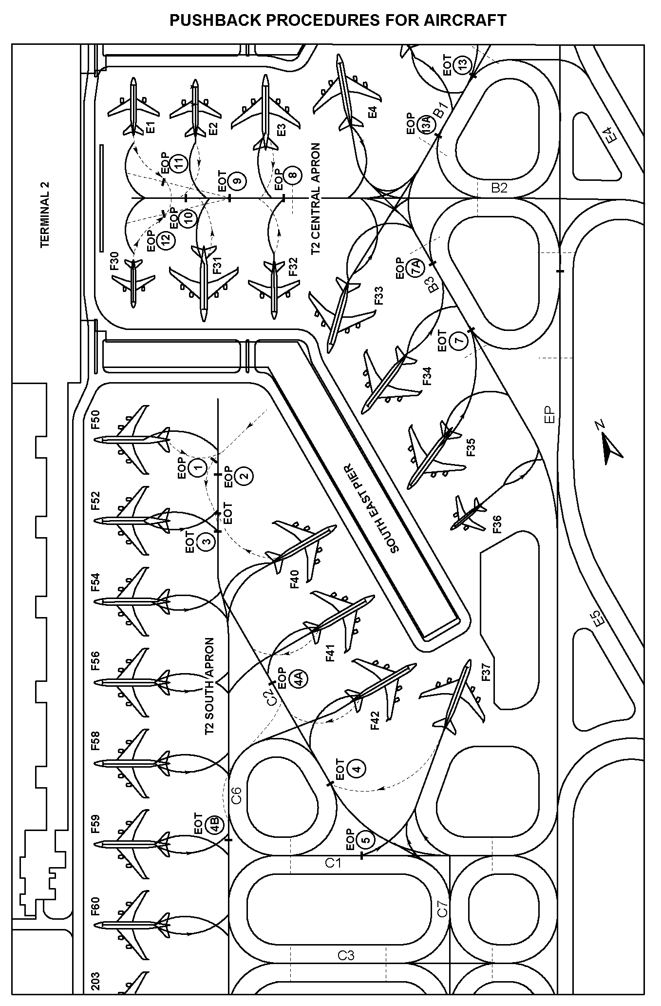
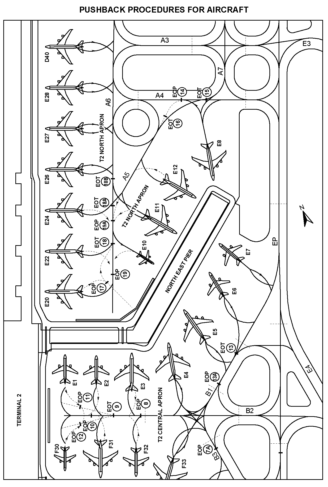
T2 CENTRAL | ||
| E1 | The aircraft (on idle thrust) shall be pushed back such that the pushback line is always kept midway between the aircraft main gear until its nosewheel is at Stopbar 12. This is marked as “END OF PUSH” on the ground. The aircraft shall then be towed forward to Stopbar 9. This is marked as “END OF TOW” on the ground. | Standard pushback approved |
| E2 | The aircraft (on idle thrust) shall be pushed back until its nosewheel is at the intersection of the lead-in line and TWY B2 centreline. The aircraft shall then be towed forward to Stopbar 9. This is marked as “END OF TOW” on the ground. | Standard pushback approved |
| E3 | The aircraft (on idle thrust) shall be pushed back until its nosewheel is at Stopbar 9. This is marked as “END OF TOW” on the ground. | Standard pushback approved |
| E4 | The aircraft (on idle thrust) shall be pushed back: | |
OR | Standard pushback approved | |
OR | Pushback approved, to pushback onto TWY B1 | |
| Pushback approved, to pushback onto TWY B3. | |
| E5, E6 | The aircraft (on idle thrust) shall be pushed back until its nosewheel is at the intersection of the lead-in line and TWY B1 centreline. The aircraft shall then be towed forward to Stopbar 13. This is marked as “END OF TOW” on the ground. | Standard pushback approved |
| E7 | The aircraft (on idle thrust) shall be pushed back until its nosewheel is at Stopbar 13. This is marked as “END OF TOW” on the ground. | Standard pushback approved |
| F30 | The aircraft (on idle thrust) shall be pushed back such that the pushback line is always kept midway between the aircraft main gear until its nosewheel is at Stopbar 11. This is marked as “END OF PUSH” on the ground. The aircraft shall then be towed forward to Stopbar 9. This is marked as “END OF TOW” on the ground. | Standard pushback approved |
| F31 | The aircraft (on idle thrust) shall be pushed back until its nosewheel is at Stopbar 10. This is marked as “END OF PUSH” on the ground. The aircraft shall then be towed forward to Stopbar 9. This is marked as “END OF TOW” on the ground. | Standard pushback approved |
| F32 | The aircraft (on idle thrust) shall be pushed back until its nosewheel is at Stopbar 9. This is marked as “END OF TOW” on the ground. | Standard pushback approved |
| F33 | The aircraft (on idle thrust) shall be pushed back: | |
OR | Standard pushback approved | |
OR | Pushback approved, to pushback onto TWY B1 | |
| Pushback approved, to pushback onto TWY B3. | |
| F34 | The aircraft (on idle thrust) shall be pushed back until its nosewheel is at the intersection of the lead-in line and TWY B3 centreline. The aircraft shall then be towed forward to Stopbar 7. This is marked as “END OF TOW” on the ground. | Standard pushback approved |
| F35 | The aircraft (on idle thrust) shall be pushed back onto Taxilane B3 to face south until its nosewheel is at the intersection of the aircraft stand lead-in line and Taxilane B3 centreline. The aircraft may breakaway from there. | Standard pushback approved |
| F35L | The aircraft (on idle thrust) shall be pushed back following the pushback line onto Taxilane B3 to face south until the nose of the aircraft is behind the stopbar behind aircraft stand F35. The aircraft may breakaway from there. | Standard pushback approved |
| F35R | The aircraft (on idle thrust) shall be pushed back following the pushback line onto Taxilane B3 to face south until its nosewheel is at the intersection of the aircraft stand pushback line and Taxilane B3 centreline. The aircraft may breakaway from there. | Standard pushback approved |
| F36 | The aircraft (on idle thrust) shall be pushed back until its nosewheel is at Stopbar 7. This is marked as “END OF TOW” on the ground. | Standard pushback approved |
| T2 NORTH | ||
| E8 | The aircraft (on idle thrust) shall be pushed back until its nosewheel is at Stopbar 14. This is marked as “END OF PUSH” on the ground. The aircraft shall then be towed forward to Stopbar 15. This is marked as “END OF TOW” on the ground. | Standard pushback approved |
| E10 | The aircraft (on idle thrust) shall be pushed back with the main gear mid-point following the pushback line until its nosewheel is at position EOP 19. | Standard pushback approved |
| E11 | Main pushback procedure (for all aircraft wingspan) | |
The aircraft (on idle thrust) shall be pushed back with the main gear mid-point following the main gear pushback line onto TWY A6 centreline. The aircraft shall then be towed forward to Stopbar 16 on TWY A5. This is marked as “END OF TOW” on the ground. | Standard pushback approved | |
Alternate pushback procedure (for aircraft with wingspan of less than 65m) | ||
The aircraft (on idle thrust) shall be pushed back with the main gear mid-point following the main gear pushback line until its body is aligned with TWY A6 centreline. | Pushback approved, to pusback onto TWY A6. | |
Alternate pushback procedure (for aircraft with wingspan of more than 65m) | ||
The aircraft (on idle thrust) shall be pushed back with the main gear mid-point following the main gear pushback line until its nosewheel is at the ‘EOP 19A’ position behind aircraft stand E24. The aircraft shall then be towed forward to ‘EOT 18B’ behind aircraft stand E26. | Pushback approved, to pushback onto TWY A6. | |
| E12 | The aircraft (on idle thrust) shall be pushed back: | |
OR | Standard pushback approved | |
| Pushback approved, to pusback onto TWY A6. | |
| E20 | The aircraft (on idle thrust) shall be pushed back with the main gear mid-point following the main gear pushback line until its nosewheel is at Stopbar 17. The aircraft shall then be towed forward to “END OF TOW” Stopbar 18A. Aircraft may breakaway from there. | Standard pushback approved |
| E22 | The aircraft (on idle thrust) shall be pushed back with the main gear mid-point following the main gear pushback line until its nosewheel is at Stopbar 19. This is marked as “END OF PUSH” on the ground. The aircraft shall then be towed forward to Stopbar 18. This is marked as “END OF TOW” on the ground. | Standard pushback approved |
| E24 | The aircraft (on idle thrust) shall be pushed back facing North until its body is aligned with TWY A6 centreline. Aircraft may breakaway from there. | Standard pushback approved |
| E24L, E24R | The aircraft (on idle thrust) shall be pushed back facing North until its body is aligned with TWY A6 centreline. Aircraft may breakaway from there. | Standard pushback approved |
| E26 | The aircraft (on idle thrust) shall be pushed back to face North until its body is aligned with TWY A6 centreline. | Standard pushback approved |
| E27, E28 | The aircraft (on idle thrust) shall be pushed back to face North (or South) until its body is aligned with TWY A6 centreline. | Pushback approved, to face North (or South). |
| T2 SOUTH | ||
| F37 | The aircraft (on idle thrust) shall be pushed back: | |
OR | Standard pushback approved | |
| Pushback approved, to face East on TWY C1. | |
| F40, F52 | The aircraft (on idle thrust) shall be pushed back until its nosewheel is at Stopbar 2. This is marked as “END OF PUSH” on the ground. The aircraft shall then be towed forward to Stopbar 3. This is marked as “END OF TOW” on the ground. | Standard pushback approved |
| F41 | The aircraft (on idle thrust) shall be pushed back: | |
OR | Standard pushback approved | |
| Pushback approved, to pushback onto TWY C6. | |
| F42 | Main pushback procedure (for all aircraft wingspan) | |
The aircraft (on idle thrust) shall be pushed back until its nosewheel is at the intersection of the lead-in line and the TWY C2 centreline. The aircraft shall then be towed forward to Stopbar 4. This is marked as “EOT 4” on the ground. | Standard pushback approved | |
Alternate pushback procedure (for aircraft with wingspan of less than 65m) | ||
The aircraft (on idle thrust) shall be pushed onto TWY C6 until its nosewheel is at the intersection of TWY C2 and TWY C6 centreline. | Pushback approved, to pushback onto TWY C6. | |
Alternate pushback procedure (for aircraft with wingspan of more than 65m) | ||
The aircraft (on idle thrust) shall be pushed back until its nosewheel is at the ‘EOP 4A’ position. The aircraft shall then be towed forward with its nosewheel following the towed forward line until its nosewheel is on the ‘EOT 4B’ position, behind aircraft stand F59. | Pushback approved, to pushback onto TWY C6. | |
| F50 | The aircraft (on idle thrust) shall be pushed back with the main gear following the main gear pushback line, facing south until its nosewheel is on the “END OF PUSH” Stopbar 1 marking painted on the ground behind aircraft stand F50. The aircraft shall then be towed forward with the nosewheel following the tow-forward line until its nosewheel is on the “END OF TOW” Stopbar 3 marking painted on the ground behind aircraft stand F52. | Standard pushback approved |
| F52L | The aircraft (on idle thrust) shall be pushed back to face south until its nosewheel is at the intersection of the aircraft pushback line and taxilane C6. | Standard pushback approved |
| F52R | The aircraft (on idle thrust) shall be pushed back to face south until its nosewheel is at the intersection of the aircraft pushback line and taxilane C6. The aircraft shall then be towed forward until its nosewheel is on the “END OF TOW” position. | Standard pushback approved |
| F54 | The aircraft (on idle thrust) shall be pushed back until its nosewheel is at a point on TWY C6 in line with the mid-point of aircraft stands F52 and F54. It shall breakaway from this position. | Standard pushback approved |
| F56 | The aircraft (on idle thrust) shall be pushed back to face South until its nosewheel is at the intersection of the aircraft pushback line and taxilane C6.The aircraft shall then be towed forward until its nosewheel is abeam aircraft stand F56. | Standard pushback approved |
| F56L, F56R | The aircraft (on idle thrust) shall be pushed back to face South until its nosewheel is at the intersection of the aircraft pushback line and taxilane C6.The aircraft shall then be towed forward until its nosewheel is abeam aircraft stand F56. | Standard pushback approved |
| F58 | The aircraft (on idle thrust) shall be pushed back to face North (or South), on TWY C6 centreline. | Pushback approved, to face North (or South). |
| F59 | The aircraft (on idle thrust) shall be pushed back to face North on TWY C6 centreline until its nosewheel is abeam aircraft stand F60. OR | Pushback approved, to face North. |
The aircraft (on idle thrust) shall be pushed back to face South on TWY C6. | Pushback approved, to face South. | |
| F59L, F59R | The aircraft (on idle thrust) shall be pushed back to face North on taxilane C6 centreline until its nosewheel is abeam aircraft stand F60. OR | Pushback approved, to face North. |
The aircraft (on idle thrust) shall be pushed back to face South on taxilane C6 centreline. | Pushback approved, to face South. | |
| F60 | The aircraft (on idle thrust) shall be pushed back to face North (or South), on TWY C6 centreline. | Pushback approved, to face North (or South). |
| 1, 2 | The aircraft (on idle thrust) shall be pushed back: | |
| Pushback approved, to face West. | |
| OR | ||
| Pushback approved, to face North. | |
| 3, 4, 5, 6, 7, 8, 9, 10 | The aircraft (on idle thrust) shall be pushed back onto TWY L5 to face North or South until its nosewheel is at the intersection of the aircraft stand lead-in line and the centreline of TWY L5. The aircraft may breakaway from there. There shall be no simultaneous pushback of aircraft unless there is at least one aircraft stand separation. Simultaneous pushback is not permitted for aircraft stands 1, 2 and 3. | Pushback approved, to face North or South. |
| 11, 12, 13 | The aircraft (on idle thrust) shall be pushed back onto TWY L5 to face North or South until its nosewheel is at the “END OF PUSH (EOP)” position and the centreline of TWY L5. The aircraft may breakaway from there. There shall be no simultaneous pushback of aircraft unless there is at least one aircraft stand separation. | Pushback approved, to face North or South. |
| 14 | The aircraft (on idle thrust) shall be pushed back onto TWY L5 to face North until its nosewheel is at the “END OF PUSH (EOP)” position and the centreline of TWY L5. The aircraft may breakaway from there. There shall be no simultaneous pushback of aircraft unless there is at least one aircraft stand separation. | Pushback approved, to face North. |
| 15, 16, 701, 702 | The aircraft (on idle thrust) shall be pushed back onto TWY L5 centreline to face North. The aircraft shall then be towed forward until its nosewheel is at the position between aircraft stands 12 and 13. The aircraft may breakaway from there. | Pushback approved, to face North. |
| 17 | The aircraft (on idle thrust) shall be pushed back to face West until its nosewheel is at the “END OF PUSH (EOP)” position. The aircraft shall then be towed forward onto TWY L5 to face North until its nosewheel is at the position between aircraft stands 12 and 13. The aircraft may breakaway from there. | Standard pushback approved. |
| SOUTH APRON | ||
| 461 | The aircraft (on idle thrust) shall be pushed back onto taxiway S1 to face west until its nosewheel is at EOP position. The aircraft may breakaway from there. There shall be no simultaneous aircraft pushback from aircraft stands 462, 462L, 462R, 463, 463L and 463R. | Pushback approved, to face west |
| 462 | The aircraft (on idle thrust) shall be pushed back onto taxiway S1 to face west until its nosewheel is at the intersection of the aircraft stand pushback line and taxiway S1 centreline. The aircraft may breakaway from there. There shall be no simultaneous aircraft pushback from aircraft stands 461, 462L, 462R, 463, 463L and 463R. | Pushback approved, to face west |
| 462L | The aircraft (on idle thrust) shall be pushed back onto taxiway S1 to face west until its nosewheel is at the intersection of the aircraft stand pushback line and taxiway S1 centreline. The aircraft may breakaway from there. There shall be no simultaneous aircraft pushback from aircraft stands 461, 462, 462R, 463, 463L and 463R. | Pushback approved, to face west |
| 462R | The aircraft (on idle thrust) shall be pushed back onto taxiway S1 to face west until its nosewheel is at the intersection of the aircraft stand pushback line and taxiway S1 centreline. The aircraft may breakaway from there. There shall be no simultaneous aircraft pushback from aircraft stands 461, 462, 462L, 463, 463L and 463R. | Pushback approved, to face west |
| 463 | The aircraft (on idle thrust) shall be pushed back onto taxiway S1 to face west until its nosewheel is at the intersection of the aircraft stand pushback line and taxiway S1 centreline. The aircraft may breakaway from there. There shall be no simultaneous aircraft pushback from aircraft stands 461, 462, 462L, 462R, 463L and 463R. | Pushback approved, to face west |
| 463L | The aircraft (on idle thrust) shall be pushed back onto taxiway S1 to face west until its nosewheel is at the intersection of the aircraft stand pushback line and taxiway S1 centreline. The aircraft may breakaway from there. There shall be no simultaneous aircraft pushback from aircraft stands 461, 462, 462L, 462R, 463 and 463R. | Pushback approved, to face west |
| 463R | The aircraft (on idle thrust) shall be pushed back onto taxiway S1 to face west until the nose of the aircraft is behind the stop bar behind aircraft stand 463L. The aircraft may breakaway from there. There shall be no simultaneous aircraft pushback from aircraft stands 461, 462, 462L, 462R, 463 and 463L. | Pushback approved, to face west |
4 ADVANCED MULTILATERATION SYSTEM
4.1 INTRODUCTION
4.2 CARRIAGE OF MODE-S SSR TRANSPONDER
4.3 MULTILATERATION SYSTEM OUTLINE
4.4 AIRCRAFT REQUIREMENTS
4.5 PROCEDURES/ACTIONS REQUIRED BY PILOTS
Pilots will be required to enter an assigned Mode A code at start-up. This code will be either a discrete or non-discrete code (a conspicuity code, e.g. 1000).
Pilots shall ensure that the aircraft transponder is operating (that is, XPNDR or the equivalent according to specific installation, AUTO if available, not OFF or STBY) and the assigned Mode A code is selected prior to the request for pushback or taxi, whichever is earlier.
Whenever the aircraft is capable of reporting aircraft identification, the aircraft identification must also be entered prior to the request for pushback or taxi, whichever is earlier, through the FMS or the Transponder Control Panel. Flight crew must use the 3-letter ICAO designator of the operator, followed by flight identification number (for example, BAW123, SIA002).
Pilots shall ensure that the aircraft transponder is operating (that is, XPNDR or the equivalent according to specific installation, AUTO if available, not OFF or STBY) after landing, and continuously until the aircraft is stationary at the aircraft stand.
Pilots shall ensure that the assigned Mode A code is not changed until the aircraft is stationary at the aircraft stand. (The system requires it for identification of the aircraft).
5 AIRFIELD GROUND LIGHTING CONTROL AND MONITORING SYSTEM (AGLCMS) AND MARKINGS
5.1 INTRODUCTION
5.2 ROUTE SELECTION AND PRIORITY
The crew have
- received positive ATC clearance to enter / cross the runway or taxiway, and
- observed that the red stop-bar lights are turned off.
5.3 INFORMATION AND MANDATORY SIGNS/MARKINGS
5.4 TAXI INSTRUCTIONS USING THE GREEN TAXIWAY CENTRELINE LIGHTS
WSSS AD 2.10 AERODROME OBSTACLES
| IN APPROACH / TKOF AREAS | IN CIRCLING AREA AND AT AD | ||||||
|---|---|---|---|---|---|---|---|
| RWY/Area affected | OBST type, ELEV, Markings/LGT | Coordinates | OBST type, ELEV, Markings/LGT | Coordinates | |||
| 1 | 2 | 3 | 1 | 2 | |||
| a) | RWY 20R APCH RWY 02L TKOF | Mast HGT ranging fm 98ft AMSL and above. | Shipping channel aprx1290m from THR RWY 20R. | a) | Surface wind direction sleeves | LOC at each end of RWY adjacent to GP hut | |
| b) | RWY 20C APCH RWY 02C TKOF | Mast HGT ranging fm 98ft AMSL and above. | Shipping channel aprx 2630m from THR RWY 20C. | b) | PAR hut | Besides RWY 02L/20R, opposite the PTB | |
| c) | RWY 02L/20R APCH RWY 02L/20R TKOF RWY 02C/20C APCH RWY 02C/20C TKOF | ILS LLZ co-located with LLZ antennas. | Within the RWY strip. | c) | Frangible PAR reflectors | Located at ends of RWY 02L/20R | |
| d) | RWY 20R APCH | Two antennae, HGT 72ft AMSL, marked and LGTD | 012311N 1035928E | d) | GP huts co-located with GP antennas | Within the RWY strip | |
| e) | RWY 20R APCH | Antenna, HGT 88ft AMSL, marked and LGTD | 012315N 1035931E | e) | Antenna, HGT 82ft AMSL, marked and LGTD | 012036N 1035819E | |
| f) | RWY 02L APCH | Antenna, HGT 82ft AMSL, marked and LGTD | 012051N 1035827E | f) | Antenna, HGT 85ft AMSL, marked and LGTD | 012039N 1035821E | |
| g) | RWY 02L APCH | Pole, HGT 128ft AMSL, marked and LGTD | 011859N 1035748E | g) | Antenna, HGT 78ft AMSL, marked and LGTD | 012042N 1035823E | |
| h) | RWY 02L APCH | Pole, HGT 160ft AMSL, marked and LGTD | 012058N 1035814E | h) | Antenna, HGT 82ft AMSL, marked and LGTD | 012053N 1035827E | |
| i) | RWY 02L APCH | Pole, HGT 131ft AMSL, marked and LGTD | 012038N 1035848E | i) | Antenna, HGT 78ft AMSL, marked and LGTD | 012049N 1035826E | |
| j) | RWY 20L APCH | Shipping channel | Aprx1600m from THR RWY 20L. | j) | Frangible poles, HGT 9ft AMSL | Installed APRX 200m from centre of RET to identify 58m away from TWY WP CL towards RWY 02L/20R | |
| Obstacles in the APCH/TKOF areas, circling area and at the aerodrome are shown on the AOC, IAC and VAC. | |||||||
WSSS AD 2.11 METEOROLOGICAL INFORMATION PROVIDED
| 1 | Associated MET Office | Singapore Changi (WSSS) |
| 2 | Hours of service | H24 |
| 3 | Office responsible for TAF preparation Periods of validity | Singapore Changi (WSSS) 12, 30 |
| 4 | Type of landing forecast, Interval of issuance | TREND |
| 5 | Briefing/consultation provided | P |
| 6 | Flight documentation, Language used | Charts or Tabular forms, English |
| 7 | Charts and other information available for briefing or consultation | S, U, P |
| 8 | Supplementary equipment available for providing information | HRPT: High Resolution Picture Transmission APT: Automatic Picture Transmission MDWR: MET Doppler Weather Radar MAINT: Second WED of every month BTN 0200-0900 ALTN period: THU following the second WED. |
| 9 | ATS units provided with information | Singapore ACC, Singapore RCC |
| 10 | Additional information | Tel: 65422837 (MET Office) |
WSSS AD 2.12 RUNWAY PHYSICAL CHARACTERISTICS
| Designations RWY NR | TRUE BRG | Dimensions of RWY | Strength (PCN) and surface of RWY and SWY | THR coordinates (THR Geoid Undulation) | THR elevation and highest elevation of TDZ of precision APCH RWY |
|---|---|---|---|---|---|
| 1 | 2 | 3 | 4 | 5 | 6 |
| 02L | 023.02° | 4000 M x 60 M | 72/F/B/W/U Bituminous concrete | 012056.26N 1035838.83E (10.29 M) | 6.66 M 6.23 M |
| 20R(Threshold displaced by 740m southwards) | 203.02° | 4000 M x 60 M | 72/F/B/W/U Bituminous concrete | 012233.95N 1035920.06E (10.29 M) | 4.01 M 4.31 M |
| 02C | 023.03° | 4000 M x 60 M | 72/F/B/W/U Bituminous concrete | 011943.51N 1035905.86E (10.28 M) | 4.32 M 4.52 M |
| 20C | 203.03° | 4000 M x 60 M | 72/F/B/W/U Bituminous concrete | 012143.37N 1035956.46E (10.28 M) | 4.58 M 4.56 M |
| Slope of RWY-SWY Transverse / Longitudinal | SWY Dimensions (m) | CWY Dimensions (m) | STRIP dimensions (m) | OFZ | Remarks |
|---|---|---|---|---|---|
| 7 | 8 | 9 | 10 | 11 | 12 |
| RWY 02L 0.76 / 0.24% | 60 X 60 | 270 X 150 | 4240 X 300 | Yes | Scheduled closure of runways (see below) |
| RWY 20R 1.45 / 0.25% | 60 X 60 | 270 X 150 | 4240 X 300 | ||
| RWY 02C 1.50 / 0.03% | 60 X 60 | 60 X 150 | 4240 X 300 | ||
| RWY 20C 1.38 / 0.07% | 60 X 60 | 60 X 150 | 4240 X 300 |
| Remarks (continued from above) | |
| Scheduled Closure of RWY 02L/20R | |
1a) | BTN 1630-2200 on every MON and THU of the month (preventive maintenance work). |
1b) | BTN 0225-0240 0630-0635 1000-1005 2300-2305 daily (inspection). |
| Scheduled Closure of RWY 02C/20C | |
2a) | BTN 1630-2200 on every first, second and fourth WED of the month (preventive maintenance work). |
2b) | BTN 0300-0315 0650-0655 1020-1025 2320-2325 daily (inspection). |
WSSS AD 2.13 DECLARED DISTANCES
| RWY Designator | Intersection Departures | TORA (m) | TODA (m) | ASDA (m) | LDA (m) | Remarks |
|---|---|---|---|---|---|---|
| 1 | 2 | 3 | 4 | 5 | 6 | 7 |
| 20R | Not applicable | 4000 | 4270 | 4060 | 3260 | Thr displaced by 740m southwards |
| W2 | 3850 | 4120 | 3910 | Not applicable | ||
| W3 | 3050 | 3320 | 3110 | Not applicable | ||
| W4 | 2600 | 2870 | 2660 | Not applicable | ||
| W5 | 2150 | 2420 | 2210 | Not applicable | ||
| 02L | Not applicable | 4000 | 4270 | 4060 | 4000 | Nil |
| W8 | 3850 | 4120 | 3910 | Not applicable | ||
| W7 | 3050 | 3320 | 3110 | Not applicable | ||
| W6 | 2600 | 2870 | 2660 | Not applicable | ||
| 20C | Not applicable | 4000 | 4060 | 4060 | 4000 | Nil |
| E2 | 3850 | 3910 | 3910 | Not applicable | ||
| E3 | 3425 | 3485 | 3485 | Not applicable | ||
| E4 | 2750 | 2810 | 2810 | Not applicable | ||
| E5 | 2250 | 2310 | 2310 | Not applicable | ||
| 02C | Not applicable | 4000 | 4060 | 4060 | 4000 | Nil |
| E10 | 3850 | 3910 | 3910 | Not applicable | ||
| E9 | 3345 | 3405 | 3405 | Not applicable | ||
| E8 | 3205 | 3265 | 3265 | Not applicable | ||
| E7 | 2555 | 2615 | 2615 | Not applicable | ||
| E6 | 2105 | 2165 | 2165 | Not applicable |
Note: Intersection departures are allowed subject to the following:
- initiated by pilot and approved by ATC, traffic permitting.
- ATC is able to keep aircraft visual at all times
WSSS AD 2.14 APPROACH AND RUNWAY LIGHTING
| RWY | Apch Lgt Type, Len Intensity | Thr Lgt colour WBAR | PAPI (MEHT) | TDZ Lgt Len | RWY Centreline Lgt Len, spacing, colour, INTST | RWY Edge Lgt, Len, spacing, colour, INTST | RWY End Lgt colour | SWY Lgt colour |
| 1 | 2 | 3 | 4 | 5 | 6 | 7 | 8 | 9 |
| 02L | CAT II High Intensity consisting of extended centreline and Red row barrettes, 2 crossbars, 2 approach beacons and sequenced flashing lights. | Green supplemented by green wing bar and 2 thr ident lights. | PAPI 003° loc either side of rwy, 422m behind rwy thr, 2 White lgt and 2 Red lgt (20.6m), 3 White lgt and 1 Red lgt (23.1m), 4 White lgt (25.6m). Acft with eye-to-wheel hgt greater than 8m are adz to fly with 2 White and 2 Red lgt visible so as to achieve sufficient wheel clearance. | White | Inset High Intensity centreline lights as flw: From thr to 900m fm rwy end: White, 300m to 900m fm rwy end: Altn Red/ White, 300m to rwy end: Red. | Bi-directional raised White/Amber edge lights. | Red | Elevated Red |
| 20R | CAT I High Intensity distance coded centreline lgts showing variable White and crossbars at 150m, 300m, 450m, 600m and 750m. | Green supplemented by green wing bar and 2 thr ident lights. | PAPI 003° located either side of rwy, 410m fm thr. 2 White lgt and 2 Red lgt (20.0m), 3 white lgt and 1 Red lgt (22.6m), 4 White lgt (25.0m). Acft with eye-to-wheel hgt greater than 8m are adz to fly with 2 White and 2 Red lgt visible so as to achieve sufficient wheel clearance. | Nil | Inset High Intensity centreline lights as flw: From thr to 900m fm rwy end: White, 300m to 900m fm rwy end: Altn Red/ White, 300m to rwy end: Red. | Red rwy edge lgts in the direction of Rwy 20R before the displaced thr. Bi-directional raised White/Amber edge lights after the displaced thr. | Red | Elevated Red |
| 02C | CAT I High Intensity consisting of centreline barrettes showing variable white, 1 crossbar, 2 approach beacons and sequenced flashing lights. | Green supplemented by green wing bar and 2 thr ident lights. | PAPI 003° located either side of rwy, 418m fm thr. 2 White lgt and 2 Red lgt (20.4m), 3 White lgt and 1 Red lgt (23.1m), 4 White lgt (25.5m). Acft with eye-to-wheel hgt greater than 8m are adz to fly with 2 White and 2 Red lgt visible so as to achieve sufficient wheel clearance. | Nil | Inset High Intensity centreline lights as flw: From thr to 900m fm rwy end: White, 300m to 900m fm rwy end: Altn red/ white, 300m to rwy end: Red. | Bi-directional raised White/Amber edge lights. | Red | Elevated Red |
| 20C | CAT II High Intensity consisting of extended centreline and red row barrettes, 2 crossbars, 2 approach beacons and sequenced flashing lights. | Green supplemented by green wing-bar and 2 THR ident lights. | PAPI 003° located left side of RWY, 418m fm THR. 2 White lgt and 2 Red lgt (19.8m), 3 White lgt and 1 Red lgt (23.7m), 4 White lgt (26.2m). Acft with eye-to-wheel hgt greater than 8m are adz to fly with 2 White and 2 Red lgt visible so as to achieve sufficient wheel clearance. | White | Inset High Intensity centreline lights as flw: From THR to 900m fm RWY end: White, 300m to 900m fm RWY end: Altn Red/White, 300m to RWY end: Red. | Bi-directional raised White/Amber edge lights. | Red | Elevated Red |
WSSS AD 2.15 OTHER LIGHTING, SECONDARY POWER SUPPLY
| 1 | ABN/IBN location, characteristics and hours of operation | ABN: 012209.22N 1035858.47E (western side of RWY 02L/20R) |
| 2 | LDI location and LGT Anemometer location and LGT | Pressure tube anemometer and wind vane situated 345m west of middle of RWY 02L/20R. Cup anemometers and wind vanes at ends and middle of both runways. Windsocks at ends of both runways. Transmissometers at both ends and in the middle of both runways |
| 3 | TWY Edge and Centreline Lighting | RWY 02L/20R and RWY 02C/20C: Blue lights on TWY curved edges and apron TWY edges and Green centreline lights on all TWY. |
| 4 | Secondary power supply/switch-over time | Automatic standby generator power supply AVBL for airfield lighting with switchover time of 1 second during Category II low visibility operations. |
| 5 | Remarks | Vehicles painted yellow or displaying chequered red/white or orange/white flag at highest point of vehicle |
WSSS AD 2.16 HELICOPTER LANDING AREA
| Refer to ENR 3.4 |
WSSS AD 2.17 ATS AIRSPACE
| 1 | Designation and Lateral Limits | CHANGI CTR 013300N 1040149E 013042N 1040654E 012542N 1040448E thence along Kuala Lumpur/Singapore FIR bdry to 012000N 1041218E 010018N 1035524E 011100N 1035134E 013300N 1040149E |
| 2 | Vertical Limits | SFC to 3,000ft ALT |
| 3 | Airspace Classification | C |
| 4 | ATS Unit Callsign Language(s) | Singapore Tower English |
| 5 | Transition Altitude | 11000 FT (3,350m) |
| 6 | Remarks | A helicopter shall not be operated within the Changi CTR unless prior permission has been obtained from the Director-General of Civil Aviation, CAAS. Email to caas_ats_ansp@caas.gov.sg |
WSSS AD 2.18 ATS COMMUNICATION FACILITIES
| Service Designation | Call sign | Frequency (P-Pri, S-Sec) | Hours of operation | Remarks |
| ACC | Singapore Radar | P123.7 MHz S127.3 MHz | H24 | for ATS Routes B469, G219, G334, R208, L625, L629, L635, L642, L644, M751, M753, M758, M761, M763, M771, N884, N891 and N892. |
| 133.8 MHz | 0000-1430 | |||
| P133.25 MHz S135.8 MHz | H24 | for ATS Routes A457, A464, A576, B466, R325 (all northbound) and R469. | ||
| P134.2 MHz S133.35 MHz | for ATS Routes , G580, L644, M646 and M767 | |||
| P134.4 MHz S128.1 MHz 255.4 MHz | for ATS Routes A464, A576, G579 (all southbound), B470, L644, N875 and in area in the immediate vicinity of Singapore. | |||
| 124.05 MHz | 0000-1530 | Flow control service provided for ARR/DEP ACFT | ||
| MAINT Period: Monthly - EV third SAT 1601-2359 | ||||
| Singapore Radio | 6556 kHz 11297 kHz | H24 | SEA 1, Emission: A3AJ. SSB suppressed carrier, SATCOM service available | |
| 5655 kHz 8942 kHz 11396 kHz | SEA 2, Emission: A3AJ. SSB suppressed carrier, SATCOM service available | |||
| 6556 kHz | SEA 3, Emission: A3AJ. SSB suppressed carrier, SATCOM service available | |||
| APP | Singapore Approach | P120.3 MHz S124.6 MHz | H24 | TAR - Intermediate approach to Singapore Changi AP and other airports in Singapore. DEP from all airports in Singapore. |
| Singapore Arrival | 119.3 MHz | TAR - Intermediate and final approach to Singapore Changi Airport. | ||
| ASR I MAINT Period: Monthly, EV first SAT 1601-2359 ASR II MAINT Period: Monthly, EV fourth SAT 1601-2359 | ||||
| TWR | Singapore Tower | 118.6 MHz | H24 0000-1600 | for TKOF/LDG. for ACFT OPR on RWY 02L/20R |
| 118.25 MHz | 0000-1600 | for ACFT OPR on RWY 02C/20C | ||
| Singapore Ground | 124.3 MHz | 1600-0000 0000-1600 | for start-up / push-back / taxiing of all aircraft for ground movement of aircraft west of Terminal 3 | |
| 121.725 MHz | 0000-1700 2100-0000 | for ground movement of aircraft east of Terminal 2 | ||
| 121.85 MHz | 0000-1800 2300-0000 | for ground movement of aircraft north of Terminal 1 | ||
| 129.95 MHz | H24 | for ground emergency | ||
| Singapore Delivery | 121.65 MHz | H24 | for Pre-flight check/ATC clearance | |
| Changi Tower / Changi Apron | 121.9 MHz | H24 | for vehicular movements on taxiways and runways. Towing of all aircraft and requests for engine runs on apron and taxiways, excluding runways, will be regulated by Changi Apron. | |
| D-ATIS | Singapore Changi Airport Information | 128.6 MHz | H24 | Data Link Service available. AP IDENT WSSS Messages comply with ARINC 623 Standards. Updating of data: H+00 to H+10 and H+30 to H+40 |
WSSS AD 2.19 RADIO NAVIGATION AND LANDING AIDS
| Type of aid and Variation | Ident | Frequency | OPR Hr | Position of Transmitting Antenna Coordinates | DME Transmitting Antenna Elevation / Remarks |
| 1 | 2 | 3 | 4 | 5 | 6 & 7 |
| SINJON DVOR/DME | SJ | 113.5 MHz CH82X | H24 | 011319.28N 1035120.08E | 201° MAG 14.5km from THR RWY 02 (Paya Lebar). Antenna HGT: 194ft AMSL. Coverage 200NM. EM: F1. Maintenance period: Third Thursday of every month between 0200-0600 |
| TEKONG DVOR/DME | VTK | 116.5 MHz CH112X | H24 | 012455.36N 1040120.17E | 023° MAG 6.4km from THR RWY 20C (Singapore Changi). Antenna HGT: 150ft AMSL. Coverage 200NM. EM: F1 Maintenance Period: Third Friday of every month between 0200-0600 |
| RWY 20C ILS LLZ | ICC | 109.7MHz | H24 | 011932.48N 1035901.20E | Located 368m (1207ft) from THR RWY 02C, along RWY centreline. Course width 3.38°. EM: A0/A2. Maintenance Period: May - October Second Friday of every month between 1600-2300 November - April Second Friday of every month between 0200-0900 |
| RWY 20C ILS GP | - | 333.2MHz | H24 | 012131.73N 1035955.72E | Located 338m (1109ft) from THR RWY 20C on left side of RWY, 120m (394ft) from RWY centreline. GP angle 3°. HGT of ILS reference datum: 17m (56ft) EM: A0/A2 |
| RWY 20C ILS DME | ICC | CH34X | H24 | 012131.73N 1035955.72E | DME co-located with GP. EM: P9 |
| RWY 20C ILS MM | - | 75MHz | H24 | 012211.94N 1040008.52E | Located 957m (3140ft) from THR RWY 20C along extended centreline of RWY. No back beam. |
| RWY 02C ILS LLZ | ICE | 108.3MHz | H24 | 012154.41N 1040001.08E | Located 368m (1207ft) from THR RWY 20C, along RWY centreline. Course width 3.38°. EM: A0/A2. Maintenance Period: May - October Second Friday of every month between 0200-0900 November - April Second Saturday of every month between 0200-0900 |
| RWY 02C ILS GP | - | 334.1MHz | H24 | 011952.11N 1035913.68E | Located 338m (1109ft) from THR RWY 02C on left side of RWY, 120m (394ft) from RWY centreline. GP angle 3°. HGT of ILS reference datum: 18m (58ft) EM: A0/A2 |
| RWY 02C ILS DME | ICE | CH20X | H24 | 011952.11N 1035913.68E | DME co-located with GP. EM: P9 |
| RWY 02C ILS MM | - | 75MHz | H24 | 011915.04N 1035853.83E | Located 945m (3100ft) from THR RWY 02C along extended centreline of RWY. No back beam. |
| RWY 20R ILS LLZ | ICH | 108.9MHz | H24 | 012045.23N 1035834.17E | Located 368m (1207ft) from THR RWY 02L, along centreline of the RWY. Course width 3.38°. EM: A0/A2. Maintenance Period: May - October First Saturday of every month between 0200-0900 November - April First Friday of every month between 0200-0900 |
| RWY 20R ILS GP | - | 329.3MHz | H24 | 012225.54N 1035912.29E | Located 330m (1083ft) from displaced THR RWY 20R on right side of the RWY, 120m (394ft) from RWY centreline. GP angle 3° . HGT of ILS REF datum: 17m (56ft) EM: A0/A2 |
| RWY 20R ILS DME | ICH | CH26X | H24 | 012225.54N 1035912.29E | DME co-located with GP. Rwy 20R ILS DME not available beyond 15 degrees west of RWY 20R centreline below 2500ft. EM: P9 |
| RWY 20R ILS MM | - | 75MHz | H24 | 012307.50N 1035934.23E | Located 1122m (3681ft) from displaced THR RWY 20R, along centreline of the RWY. |
| RWY 02L ILS LLZ | ICW | 110.9MHz | H24 | 012307.03N 1035934.03E | Located 1105m (3625ft) from displaced THR RWY 20R, along centreline of RWY. Course width 2.81° EM:A0/A2 Maintenance Period: May - October First Friday of every month between 0200-0900 November - April First Saturday of every month between 0200-0900 |
| RWY 02L ILS GP | - | 330.8MHz | H24 | 012108.34N 1035838.94E | Located 343m (1125ft) from THR RWY 02L on left side of RWY, 143m (469ft) from RWY centreline. GP angle 3° HGT of ILS Reference datum: 18m (58ft) EM:A0/A2 |
| RWY 02L ILS DME | ICW | CH46X | H24 | 012108.34N 1035838.94E | DME co-located with GP EM:P9 |
| RWY 02L ILS MM | - | 75MHz | H24 | 012027.53N 1035826.70E | Located 957m (3140ft) from THR RWY 02L along extended centreline of RWY. No back beam. |
WSSS AD 2.20 LOCAL TRAFFIC REGULATIONS
1 DESIGNATION OF PAYA LEBAR AIRPORT AS AN ALTERNATE AERODROME FOR SINGAPORE CHANGI AIRPORT
2 WRONG APPROACHES AND LANDINGS OF AIRCRAFT BOUND FOR SINGAPORE CHANGI AND PAYA LEBAR AIRPORTS
2.1 INTRODUCTION
2.2 POINTS TO BEAR IN MIND WHEN APPROACHING SINGAPORE CHANGI AIRPORT OR PAYA LEBAR
The runways at Singapore Changi Airport and Paya Lebar Airport are identically aligned on 02/ 20. Therefore exercise extreme vigilance when leaving NYLON or SAMKO Holding Areas inbound and maintain correct tracks to the respective runways as listed below.
Adhere strictly to IFR procedures even in VMC which calls for a procedure turn over NYLON Holding Area or SAMKO Holding Area as prescribed.
Make full use of all available navigational and landing aids available and positively identify every aid used.
Switch to the correct ILS localizer frequency at Singapore Changi Airport under all conditions.
2.3 AERODROME CHARACTERISTICS OF SINGAPORE CHANGI AND PAYA LEBAR AIRPORTS
| Aeronautical Service | PAYA LEBAR Airport | SINGAPORE CHANGI Airport | Significant Differences and Remarks |
|---|---|---|---|
| Magnetic heading of RWY | 02/20 | 02L/20R 02C/20C | Exercise caution due to similar RWY alignment |
| Approach Lights | RWY 02 Modified Calvert High INTST with centreline and 3 crossbars. High INTST white LGT with brilliancy control and sequenced flashing lights. | RWY 02L Precision APCH LGT CAT II. Extended centreline with red side row barettes, 2 crossbars, 2 APCH beacons and sequenced flashing lights. | |
| RWY 20 Modified Calvert High INTST with centreline and 3 crossbars. High INTST white LGT with brilliancy control and sequenced flashing lights. | RWY 20R Precision APCH LGT CAT I. Centreline barettes flashing white, 2 APCH beacons and sequenced flashing lights. (refer to chart AD-2-WSSS-ADC-2) | ||
| ILS | RWY 20 - Nil | RWY 20R IDENT ICH No back beam LLZ 108.9 MHz GP 329.3 MHz | |
| RWY 02 - Nil | RWY 02L IDENT ICW No back beam LLZ 110.9 MHz GP 330.8 MHz | ||
| IBN | Flashing R ‘PL’ HN and IMC | Flashing G ‘CH’ HN and IMC | |
| ABN | Nil | ALTN Flashing W G every 2.3 SEC |
WSSS AD 2.21 NOISE ABATEMENT PROCEDURES
WSSS AD 2.22 FLIGHT AND GROUND PROCEDURES
1 LOW VISIBILITY PROCEDURES (LVP) FOR CATEGORY II ILS OPERATIONS
1.1 Introduction
1.2 Authorisation for Category II ILS Approaches
1.3 Category II ILS Runways
1.4 Initiation of Category II ILS Operations
1.5 ILS Sensitive Areas
1.6 Termination of LVP for Category II ILS Operations
1.7 Operations of flights Not Authorised for Category II ILS
Operations
2 RUNWAY UTILISATION
2.1 Runway-in-use
2.2 Departures
2.3 Clearance for Immediate Take-Off
- if waiting clear of the runway, taxi immediately on to it and begin take-off run immediately without stopping the aircraft;
- if already lined-up on the runway, take-off without delay;
- if unable to comply with the instruction, inform ATC immediately.
2.4 Arrivals - Minimum Runway Occupancy Time (ROT)
| RWY | Exit Taxiway (LED in metres) | Remarks |
|---|---|---|
| 20R | W6*(1655), W7*(2123) and W8 (3061) | Note 1: Recommended exit taxiways are bold and underlined. Note 2: * Indicates Rapid Exit Taxiway (RET) and maximum design ground speed for the exit taxiway is 50kts. |
| 20C | E6*(1948), E7*(2391) and E8 (3152) | |
| 02L | W5*(1966), W4*(2491) and W3* (2876) | |
| 02C | E5*(2055), E4*(2565) and E3* (3267) |
2.5 Land after Procedures
- the runway is long enough;
- during daylight hours;
- the second aircraft will be able to see the first aircraft clearly and continuously until it is clear of the runway;
- the second aircraft has been warned.
2.6 Special Landing Procedures
- When the runway-in-use is temporarily occupied by other traffic, landing clearance may be issued to an arriving aircraft provided that at the time the aircraft crosses the threshold of the runway-in- use the following separation distances will exist:
- Landing following landing - The preceding landing aircraft will be clear of the runway-in-use or will be at least 2,500m from the threshold of the runway-in-use.
- Landing following departure - The departing aircraft will be airborne and at least 2,500m from the threshold of the runway-in-use, or if not airborne, will be at least 2,500m from the threshold of the runway-in-use.
- during daylight hours;
- visibility of at least 5km;
- cloud ceiling of 1,500ft in the departure/missed approach area;
- ATC is satisfied that the pilot of the next arriving aircraft will be able to observe continuously the relevant traffic;
- no unfavourable surface wind conditions (including significant tailwind, windshear, turbulence, etc);
- when the runway is dry and free of all precipitants such that there is no evidence that the braking action may be adversely affected.
2.7 Phraseology
.... (call sign) .... after the landing / departing .... (Aircraft Type) Runway .....(Designator) cleared to land.
3 AIRPORT COLLABORATIVE DECISION MAKING (A-CDM) MODE OF OPERATIONS
- Target Off Block Time (TOBT) – The time an aircraft operator (AO) or ground handling agent (GHA) estimates that an aircraft will be ready, all doors closed, boarding bridge removed, pushback vehicle available and ready to start-up / pushback immediately upon receipt of clearance from ATC.
- Target Start Up Approval Time (TSAT) – The time provided by ATC that an aircraft can expect start-up / push back approval.
- Calculated Take Off Time (CTOT) – A time calculated as a result of tactical slot allocation, at which a flight is expected to become airborne.
4 A-CDM PRE-DEPARTURE PROCEDURES
- Airport Operations Centre System (AOCS) A-CDM web based portal; or
- Gate Message Input Display (GMID) at boarding rooms;
- AOCS A-CDM portal;
- GMID;
- Aircraft Docking Guidance System (ADGS) at contact stands;
- Radio communication with GHA or AO.
- AOCS A-CDM portal;
- GMID;
- ADGS at contact stands;
- Radio communication with GHA or AO;
- ATC - Upon issuance of ATC clearance (for flights parked at aircraft stands without ADGS).
5 A-CDM START-UP PROCEDURES
- Callsign
- Destination
- Proposed flight level and alternate level, if any
- Parking position
- Pilot shall only request for ATC clearance provided aircraft is ready to pushback at TOBT. Any updates to TOBT after receipt of ATC clearance will result in cancellation of clearance issued as the ATC clearance validity is based on the initial TOBT.
- ATC may swap pushback sequence based on real-time readiness of aircrafts to maximise apron and runway capacity and reduce the overall delay to traffic as and when required.
- At the end of pushback, the departing aircraft must have all engines started and be ready to taxi immediately, unless otherwise instructed by ATC.
Note: The first aircraft to taxi may not necessarily be the first aircraft to take-off as distances between aircraft stands and the departure runway vary.
- ATC will inform the aircraft when a clearance is cancelled using the phraseology; “(Callsign of aircraft) your ATC clearance and TSAT is cancelled (reason). Update TOBT before requesting for new clearance”.
- Flight may also have its ATC clearance cancelled if it develops a technical problem after pushback and is unable to taxi for prolonged duration.
6 A-CDM INFORMATION VIA AIRCRAFT DOCKING GUIDANCE SYSTEM (ADGS)
| Aircraft Docking Guidance System (ADGS) | |
|---|---|
| Description | Display on ADGS |
Aircraft arrival to stand
|  |
40 minutes prior to TOBT
|  |
25 minutes prior to TOBT
|  |
Aircraft departure from stand
|  |
7 CONTACT AND INFORMATION
8 ASSIGNMENT OF FLIGHT LEVELS TO AIRCRAFT DEPARTING FROM SINGAPORE CHANGI AIRPORT
- Aircraft departing Singapore will be cleared to FL280;
- Succeeding aircraft on the same route will be cleared to FL280 with 10min longitudinal separation provided there is no closing speed with the preceding aircraft;
- Additional longitudinal separation as appropriate shall be imposed by ATC when the succeeding aircraft is faster than the preceding aircraft on the same route;
- The first aircraft from either Singapore or Kuala Lumpur to be over GUNIP on N571 or N571/N877, the Kuala Lumpur/Bangkok FIR boundary on M770 or L759 and VPL on P628 can expect its requested flight level
9 DELAY IN PUSHBACK AND/OR TAXIING DUE TO OTHER AIRCRAFT
Note: The TSAT may not be able to predict delays arising from apron congestion as traffic movement on ground is dynamic and situations may change on a real time basis depending on aircraft readiness. ATC will facilitate pushback as soon as possible when traffic permits.
10 DELAY IN TAKE-OFF DUE TO RESTRICTIONS IN THE ATC CLEARANCE
11 DELAY DUE TO OVERFLIGHTS
12 NON-CDM MODE OF OPERATIONS
- Pilots shall notify ATC when the aircraft is ready to pushback within 5 minutes.
- ATC will advise the pilot whether the proposed flight level or other alternate flight level is available and an ATC clearance will be issued accordingly. If pre-departure coordination with an adjacent unit or centre is required, the pilot will be instructed to standby.
- Once flight level is accepted by the pilot and an ATC clearance issued, the aircraft must be pushed back within 5 minutes from the time the ATC clearance is accepted unless other ATC restrictions are imposed. The ATC clearance will be cancelled on expiry of the 5 minutes grace period. This also applies to situations when aircraft return to blocks after pushback or develop technical issues and is unable to continue taxi.
- Pilots who are ready to depart following the cancellation of an ATC clearance will adopt the procedures as if it is the first time they are ready to depart.
- AO and GHA shall continue to submit TOBT and pilots shall request for ATC clearance 5 minutes within TOBT stated in para 5.3
- ATC will revert to the gate hold procedures stated in para 13 and issue estimated pushback times accordingly.
13 GATE HOLD PROCEDURES FOR DEPARTING AIRCRAFT (DURING NON-CDM MODE OF OPERATIONS)
PROCEDURES FOR PUSH BACK AND ASSIGNMENT OF FLIGHT LEVELS TO AIRCRAFT DEPARTING FROM SINGAPORE CHANGI AIRPORT
- aircraft departing Singapore will be cleared to FL280;
- succeeding aircraft on the same route will be cleared to FL280 with 10 min longitudinal separation provided there is no closing speed with the preceding aircraft;
- additional longitudinal separation as appropriate shall be provided by ATC for the faster aircraft following a slower aircraft on the same route;
- the first aircraft from either Singapore or Kuala Lumpur to be over GUNIP on N571 or N571/N877, the Kuala Lumpur/Bangkok FIR boundary on M770 or L759 and VPL on P628 can expect its requested flight level.
- callsign
- destination
- proposed flight level and alternate level, if any
- parking position
Note: The first aircraft to taxi may not necessarily be the first aircraft to take-off as distances between aircraft stands and the departure runway vary.
GATE HOLD PROCEDURES FOR DEPARTING AIRCRAFT
DELAY IN PUSH BACK AND/OR TAXIING DUE TO OTHER AIRCRAFT
DELAY IN TAKE-OFF DUE TO RESTRICTIONS IN THE ATC CLEARANCE
DELAY DUE TO OVERFLIGHTS
FLIGHTS EXEMPTED
CANCELLATION OF ATC CLEARANCE / OBTAINING A FRESH CLEARANCE
- on expiry of the 5 minutes grace period under para 3.7, it is still unable to push back; or
- after pushing back, the pilot advises that it is returning to blocks; or
- it develops a technical problem and is unable to continue taxiing.
“(Callsign of aircraft) your ATC clearance is cancelled (reason)”
14 GROUND MOVEMENT PLANNER ON VHF 121.65MHz
15 GROUND MOVEMENT CONTROL ON VHF 124.3MHz, 121.85MHz AND 121.725MHz
- Request and obtain taxi instructions prior to taxiing;
Note: ATC clearance, including the assigned SSR code will normally be issued prior to push back. Pilot shall squawk the SSR code immediately when airborne.
- Change from Ground Movement Control frequency to the Runway Control frequency when instructed (118.6MHz or 118.25MHz). It should be noted that when instructed to monitor Singapore Tower frequencies, pilots shall not establish contact with Singapore Tower; rather, pilots shall maintain a listening watch on the assigned Singapore Tower frequency and wait for instruction. This is to prevent unnecessary frequency congestion.
16 TAXIING
17 TAKE-OFF AND LANDING
RWY 02C - TWY E10 or E11
RWY 02L - TWY W8, W9 or W10
RWY 20C - TWY E1, E2
RWY 20R - TWY W1, W2
18 RNAV(GNSS) SIDs and STARs
18.1 INTRODUCTION
18.2 ARRIVALS
- A TRANSITION route; and
- An ARRIVAL route.
| ATS Route | Transition | Transition Route | RNAV STAR |
| B469 (southbound to Singapore) L642 N892 | BIKTA VEPLI MABAL | BIKTA-PIBAP-PASPU VEPLI-VINIL-PIBAP-PASPU MABAL-KILOT-VINIL-PIBAP-PASPU | PASPU ARRIVAL |
| A464 (southbound to Singapore) A576 (southbound to Singapore) R469 | ARAMA REKOP no transition | ARAMA-BOBAG REKOP-BOBAG no transition | BOBAG ARRIVAL |
| G579 | no transition | no transition | REMES ARRIVAL |
| L504 M635 M774 | OBDOS SURGA OBDOS | OBDOS-IKAGO-IKIMA-IBULA-LAVAX SURGA-IKAGO-IKIMA-IBULA-LAVAX OBDOS-IKAGO-IKIMA-IBULA-LAVAX | LAVAX ARRIVAL |
| M767 / G580 M646 / G580 G580 | TOMAN | TOMAN-KARTO-KEXAS-LAVAX | |
| Note: Aircraft landing at Singapore Changi Airport operating on N891, M753 and L642 shall flight plan only on L642 after ENREP | |||
- Vertical restrictions, designed to contain aircraft in controlled airspace and to separate aircraft from obstacles and to avoid, to the degree possible, conflict with departing traffic.
- Speed restrictions, designed for flow control purposes.
- Minimum safe altitude (MSA) within 25NM of VTK and SJ DVOR/DME. The MSA provides a minimum of 1000ft vertical clearance within 5NM of any obstacle.
- ARRIVAL identifier;
- TRANSITION identifier;
- Runway-in-use;
- An assigned level
18.3 DEPARTURES
There will be 3 Transitions as shown below:
| ATS Route | Transition | Transition Route | RNAV SID |
| L504 | BAVUS | VENPA-ATKAX-BAVUS | VENPA DEPARTURE |
| M635 | SURGA | VENPA-VENIX-SURGA | |
| M774 | KADAR | VENPA-ATKAX-KADAR |
Example:
<Callsign> cleared to Brisbane via VENPA 1A departure Transition KADAR, airway M774, flight plan route, maintain FL330, squawk alfa 2234 on departure.
18.4 TRANSITION
18.5 VERTICAL AND SPEED RESTRICTIONS
18.6 OPERATORS’ PROCEDURES
19 COORDINATES OF SID/STAR WAYPOINTS (WGS84 DATUM)
| Name | Latitude | Longitude | Radius/Distance from VTK | Radius/DIstance from SJ |
|---|---|---|---|---|
| ABVIP | 010008N | 1035032E | VTK R-203.5 / D27.0 | SJ R-183.5 / D13.2 |
| ADMIM | 005733N | 1033033E | VTK R-228.4 / D41.2 | SJ R-232.8 / D26.1 |
| AGROT | 010108N | 1035808E | VTK R-187.7 / D24.0 | SJ R-150.8 / D14.0 |
| AGVAR | 014719N | 1034145E | VTK R-318.8 / D29.8 | SJ R-344.3 / D35.3 |
| AKMET | 015355N | 1034339E | VTK R-328.6 / D34.0 | SJ R-349.3 / D41.3 |
| AKOMA | 014522N | 1035443E | VTK R-342.0 / D21.4 | SJ R-006.2 / D32.0 |
| ALFA | 013033N | 1034942E | VTK R-295.7 / D12.9 | SJ R-354.8 / D 17.2 |
| ANITO | 001700S | 1045200E | VTK R-153.4 / D113.4 | SJ R-146.0 / D108.6 |
| ARAMA | 013654N | 1030712E | VTK R-282.4 / D55.5 | SJ R-298.0 / D50.0 |
| AROSO | 020846N | 1032421E | VTK R-319.9 / D57.4 | SJ R-334.0/ D61.7 |
| ASUNA | 005948N | 1030954E | VTK R-244.1 / D57.3 | SJ R-252.0 / D43.6 |
| ATKAX | 000512N | 1065946E | VTK R-113.9 /D 195.5 | SJ R-109.7 / D200.6 |
| ATRUM | 013256N | 1040057E | VTK R-357.3 / D8.0 | SJ R-026.1 / D21.8 |
| BAVUS | 000000N | 1090000E | VTK R-105.9 / D310.5 | SJ R-103.4 / D317.3 |
| BETBA | 013302N | 1035331E | VTK R-316.1 / D11.3 | SJ R-006.3 / D19.8 |
| BIDUS | 013554N | 1035755E | VTK R-326.0 / D13.2 | SJ R-006.9 / D22.6 |
| BIKTA | 024337N | 1034308E | VTK R-346.9 / D80.4 | SJ R-355.0 / D90.2 |
| BIPOP | 013122N | 1041018E | VTK R-054.5 / D11.0 | SJ R-046.8 / D26.2 |
| BOBAG | 010230N | 1032954E | VTK R-234.7 / D38.6 | SJ R-243.2 / D24.0 |
| BOKIP | 010421N | 1034353E | VTK R-220.5 / D27.0 | SJ R-219.5 / D11.6 |
| BTM | 010813N | 1040758E | VTK R-158.2 / D17.9 | SJ R-107.0 / D17.5 |
| DIVSA | 011105N | 1040303E | VTK R-172.9 / D13.9 | SJ R-100.8 / D11.9 |
| DOGRA | 010525N | 1041423E | VTK R-146.2 / D23.5 | SJ R-108.9 / D24.4 |
| DOKTA | 012606N | 1041040E | VTK R-083.0 / D9.4 | SJ R-057.0 / D23.2 |
| DONDI | 011252N | 1035855E | VTK R-191.3/ D12.3 | SJ R-093.4 / D7.6 |
| DOSNO | 004757N | 1041409E | VTK R-160.8 / D39.0 | SJ R-137.8 / D34.1 |
| DOSPA | 011459N | 1040441E | VTK R-161.4 / D10.5 | SJ R-082.9 / D13.5 |
| DOVAN | 011938N | 1041249E | VTK R-114.6 / D12.7 | SJ R-073.9 / D22.5 |
| HOSBA | 011948N | 1042418E | VTK R-102.5 / D23.6 | SJ R-079.0 / D33.7 |
| IBIBI | 011503N | 1035707E | VTK R-203.1 / D10.7 | SJ R-073.4 / D6.0 |
| IBIVA | 011351N | 1035637E | VTK R-203.1/ D12.0 | SJ R-084.3 / D5.3 |
| IBIXU | 011621N | 1035740E | VTK R-203.2 / D9.3 | SJ R-064.4 / D7.0 |
| IBULA | 005036N | 1043600E | VTK R-134.5 / D48.7 | SJ R-116.8 / D50.2 |
| IGNON | 010847N | 1041257E | VTK R-144.1 / D19.8 | SJ R-101.8 / D22.2 |
| IKAGO | 003816N | 1052931E | VTK R-117.7 / D99.8 | SJ R-109.5 / D104.4 |
| IKIMA | 004314N | 1045500E | VTK R-127.6 / D67.9 | SJ R-115.1 / D70.5 |
| JB (JAYBEE) | 013000N | 1034242E | VTK R-285.1 / D19.3 | SJ R-332.6 / D18.6 |
| KADAR | 000647S | 1074342E | VTK R-112.4 / D240.5 | SJ R-109.0 / D245.8 |
| KARTO | 011124N | 1053343E | VTK R-098.3 / D93.5 | SJ R-091.1 / D102.6 |
| KEXAS | 011019N | 1044818E | VTK R-107.2 / D49.2 | SJ R-093.0 / D57.2 |
| KILOT | 030217N | 1044023E | VTK R-022.0 / D104.5 | SJ R-024.4 / D119.0 |
| LAVAX | 010950N | 1042714E | VTK R-120.1 / D30.0 | SJ R-095.5 / D36.2 |
| LEDOX | 011642N | 1035651E | VTK R-208.6 / D9.4 | SJ R-058.5 / D6.5 |
| LEGAS | 011524N | 1035618E | VTK R-207.9 / D10.8 | SJ R-067.3 / D5.4 |
| LELIB | 012729N | 1032450E | VTK R-274.0 / D36.6 | SJ R-298.0 / D30.0 |
| LETGO | 011411N | 1035548E | VTK R-207.3 / D12.1 | SJ R-079.1 / D4.6 |
| MABAL | 032826N | 1051236E | VTK R-030.1 / D142.1 | SJ R-031.2 / D157.2 |
| MASBO | 020248N | 1025251E | VTK R-299.0 / D78.3 | SJ R-310.2 / D76.6 |
| NYLON | 013657N | 1040624E | VTK R-023.0 / D13.0 | SJ R-032.9 / D30.0 |
| OBDOS | 002503N | 1065551E | VTK R-108.9 / D184.5 | SJ R-104.7 / D190.7 |
| PALGA | 011059N | 1034759E | VTK R-223.8 / D19.3 | SJ R-235.1 / D4.1 |
| PAMSI | 010459N | 1034845E | VTK R-212.3 / D23.6 | SJ R-197.2 / D8.7 |
| PASPU | 015915N | 1040618E | VTK R-008.3 / D34.5 | SJ R-018.3 / D48.1 |
| PIBAP | 023023N | 1040618E | VTK R-004.4 / D65.3 | SJ R-011.1 / D78.1 |
| POSUB | 012725N | 1040748E | VTK R-069.0 / D6.9 | SJ R-049.8 / D21.7 |
| PU | 012524N | 1035600E | VTK R-275.2 / D5.4 | SJ R-021.1 / D13.0 |
| REMES | 004342N | 1035735E | VTK R-185.2 / D41.2 | SJ R-167.9 / D30.2 |
| REPOV | 001623N | 1040300E | VTK R-178.6 / D68.2 | SJ R-168.3 / D57.9 |
| RUVIK | 011422N | 1042033E | VTK R-118.8 / D21.9 | SJ R-088.0 / D29.2 |
| RWY 02C DER | 012152N | 1040000E | VTK R-203.5 / D3.3 | SJ R-046.0 / D12.2 |
| RWY 02L DER | 012305N | 1035933E | VTK R-224.1 / D2.5 | SJ R-040.6 / D12.8 |
| RWY 20C DER | 011935N | 1035902E | VTK R-203.3 / D5.8 | SJ R-051.5 / D10.0 |
| RWY 20R DER | 012047N | 1035835E | VTK R-213.7 / D4.9 | SJ R-044.8 / D10.4 |
| SABKA | 015051N | 1031713E | VTK R-300.4 / D51.2 | SJ R-317.7 / D50.7 |
| SAMKO | 010530N | 1035255E | VTK R-203.5 / D21.1 | SJ R-168.0 / D8.0 |
| SANAT | 010749N | 1035930E | VTK R-186.1 / D17.1 | SJ R-123.7 / D9.9 |
| SJ (SINJON) | 011319N | 1035120E | - | - |
| SURGA | 003657S | 1063119E | VTK R-129.1 / D193.3 | SJ R-124.6 / D194.3 |
| TOKIM | 012933N | 1040315E | VTK R-022.7 / D5.0 | SJ R-036.7 / D20.1 |
| TOMAN | 012147N | 1054717E | VTK R-091.7 / D106.2 | SJ R-085.9 / D116.5 |
| TOPOM | 012955N | 1040227E | VTK R-012.8 / D5.1 | SJ R-034.2 / D20.0 |
| VENIX | 002156S | 1060521E | VTK R-130.6 / D163.5 | SJ R-125.3 / D164.3 |
| VENPA | 002141N | 1044955E | VTK R-142.3 / D79.6 | SJ R-131.2 / D78.1 |
| VEPLI | 035223N | 1040542E | VTK R-001.7 / D146.8 | SJ R-005.2 / D158.9 |
| VINIL | 025500N | 1040618E | VTK R-003.2 / D89.8 | SJ R-008.5 / D102.3 |
| VMR | 022318N | 1035218E | VTK R-351.2 / D58.8 | SJ R-000.9 / D69.6 |
| VTK (TEKONG) | 012455N | 1040120E | - | - |
20 ARRIVING AIRCRAFT
21 LIGHT AIRCRAFT OPERATIONS
- Prior permission has been granted;
- Aircraft is suitably equipped;
- Pilot is appropriately rated;
- Subject to ATC.
WSSS AD 2.23 ADDITIONAL INFORMATION
1 BIRD CONCENTRATION IN THE VICINITY OF THE AIRPORT
| - | cattle egrets | (weighing approximately 300g each) |
| - | grey herons | (weighing approximately 500g each) |
| - | brahminy kites | (weighing approximately 600g each) |
WSSS AD 2.24 CHARTS RELATED TO AN AERODROME

RNAV(GNSS) SIDs and STARs - Introduction